Kollmorgen - December 2011 283
MMC Smart Drive Hardware Manual - DRIVE RESIDENT DIGITAL MMC CONTROL
12.5.5 General I/O Port (C5)
The 26-pin HD male D-sub General I/O Port connector (labeled “C5” on the front of
the Control) provides connection between user I/O devices and the Control. This port
provides 8 source-only, 250ma, short-circuit protected outputs (described in detail in
section 12.5.5.1 on page 288), and 8 source-only inputs (described in detail in section
12.5.5.2 on page 290).
• Pin descriptions are provided in Table 12-17
• Pin assignments are provided in Table 12-18
• The available Flying Lead cable is described in Table 12-19.
• Available Breakout Boxes and Cables are described in Table 12-20.
• Breakout Box dimensions are shown in Figure 12-5
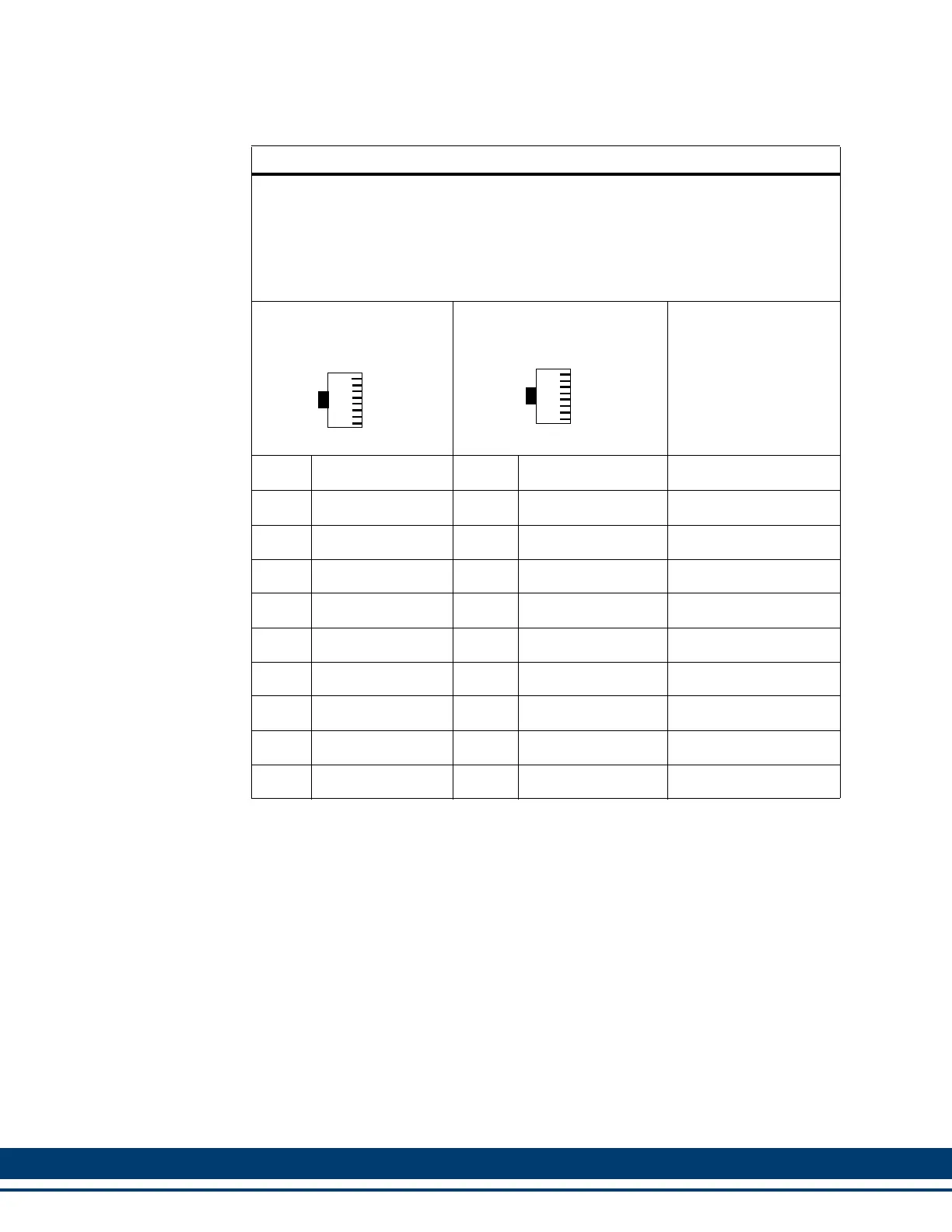
Table 12-16: Ethernet Port to Ethernet Device Cables
Part Numbers:
.3 M (1.0 ft): M.1302.8285 .6 M (2.0 ft): M.1302.8286
1 M (3.3 ft): M.1302.8287 2 M (6.6 ft): M.1302.8288
3 M (9.8 ft): M.1302.8289 5 M (16.4 ft): M.1302.8300
10 M (32.8 ft): M.1302.8301 15 M (49.2 ft): M.1302.8302
30 M (98.4 ft): M.1302.8303
Cable type: 28 AWG, shielded, twisted pair, 8 conductor.
8-Pin RJ-45 Plug (to
Ethernet Port, face view)
8-Pin RJ-45 Plug (to
Ethernet Device, face view)
Pin Signal Pin Signal Notes
1 Transmit Data + 1 Receive Data + Twisted
2 Transmit Data - 2 Receive Data - Pair
3 Receive Data + 3 Transmit Data + Twisted
6 Receive Data - 6 Transmit Data - Pair
4 None 4 None Twisted
5 None 5 None Pair
7 None 7 None Twisted
8 None 8 None Pair
Shell Drain Shell Drain
1
8
1
8
 Loading...