284 Kollmorgen - December 2011
MMC Smart Drive Hardware Manual - DRIVE RESIDENT DIGITAL MMC CONTROL
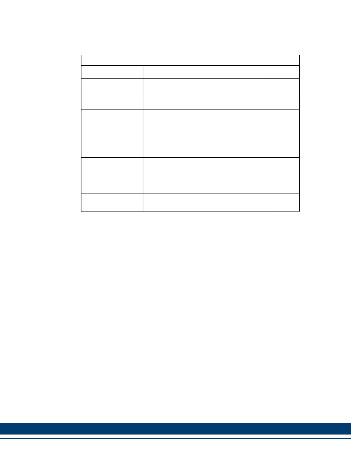
Table 12-17: General I/O Port Pin Descriptions
Function Notes Pin
DC Outputs 1-8
Nominal 24 Vdc Outputs capable of sourcing
up to 250 ma.
1-8
DC Inputs 1-8 Nominal 24 Vdc sourcing Inputs 19-26
DC Output Power
This is the 24 Vdc supplied by the user to
power the DC Outputs
9
I/O 24 Volts
These pins are only connected to each other
within the Control. If used, connect one pin to
24 Vdc, and the other pins to one side of input
devices.
10-13
24 Vdc Common
These pins are only connected to each other
within the Control. Connect pin 14 to 24V
Common. This provides the return path for the
24 Vdc Inputs. Connect pins 15-18 to one side
of output devices if desired.
14-18
Shield Ground
Provides a path for shield current through the
chassis to an external single point ground.
Shell
 Loading...