Kollmorgen - December 2011 131
MMC Smart Drive Hardware Manual - 460V 3 PHASE MMC SMART DRIVE NEXTGEN
6.1.3 Digital Link Ports
The two 8-pin RJ-45 Digital Link Port connectors (labeled “IN” and “OUT” on the front
of the Drive) provide communications between the Drive and other Digital Link
devices (another Digital Drive, a Standalone MMC Digital Control, Slice I/O Coupler,
DL-DIU, etc.). There is a green "Link" light located in the upper-right corner of each
connector. If this light is on, another Digital Link device is properly connected to the
associated "IN" or "OUT" port.
A “straight-through” shielded cable must be used when connecting the Drive to other
Digital Link devices. Connect a cable from another Digital Link device’s "OUT" port to
the Drive’s “IN” port, and another cable from the Drive’s “OUT” port to the next Digital
Link device’s "IN" port.
• Pin descriptions for are provided in Table 6-1
• Pin assignments are provided in Table 6-2
• The available Digital Link Port to Digital Drive cables are described in Table 6-3
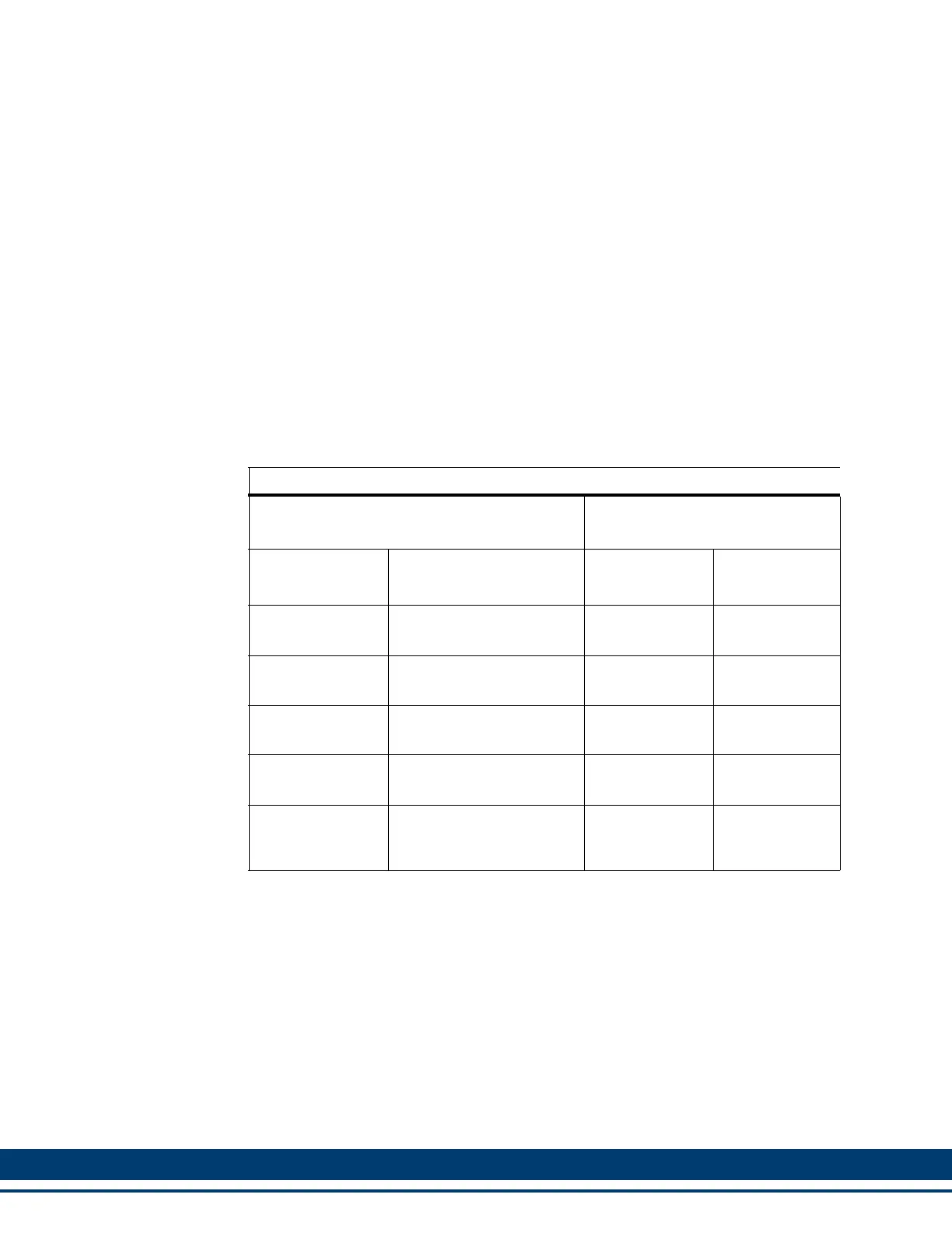
Table 6-1: Digital Link Port Pin Description
Digital Link Connector (IN/OUT)
Signals
Pin
Function Notes
“In”
Connector
“Out”
Connector
Receive Data +
Receives data from con-
nected drives.
1 3
Receive Data -
Receives data from con-
nected drives.
2 6
Transmit Data +
Transmits data to con-
nected drives.
3 1
Transmit Data -
Transmits data to con-
nected drives.
6 2
Protective
Ground
Provides a path for the
ground signal to an exter-
nal single point ground.
Connector Shell
Connector
Shell
 Loading...