Kollmorgen - December 2011 111
MMC Smart Drive Hardware Manual - 230V 1/3 PHASE MMC SMART DRIVE
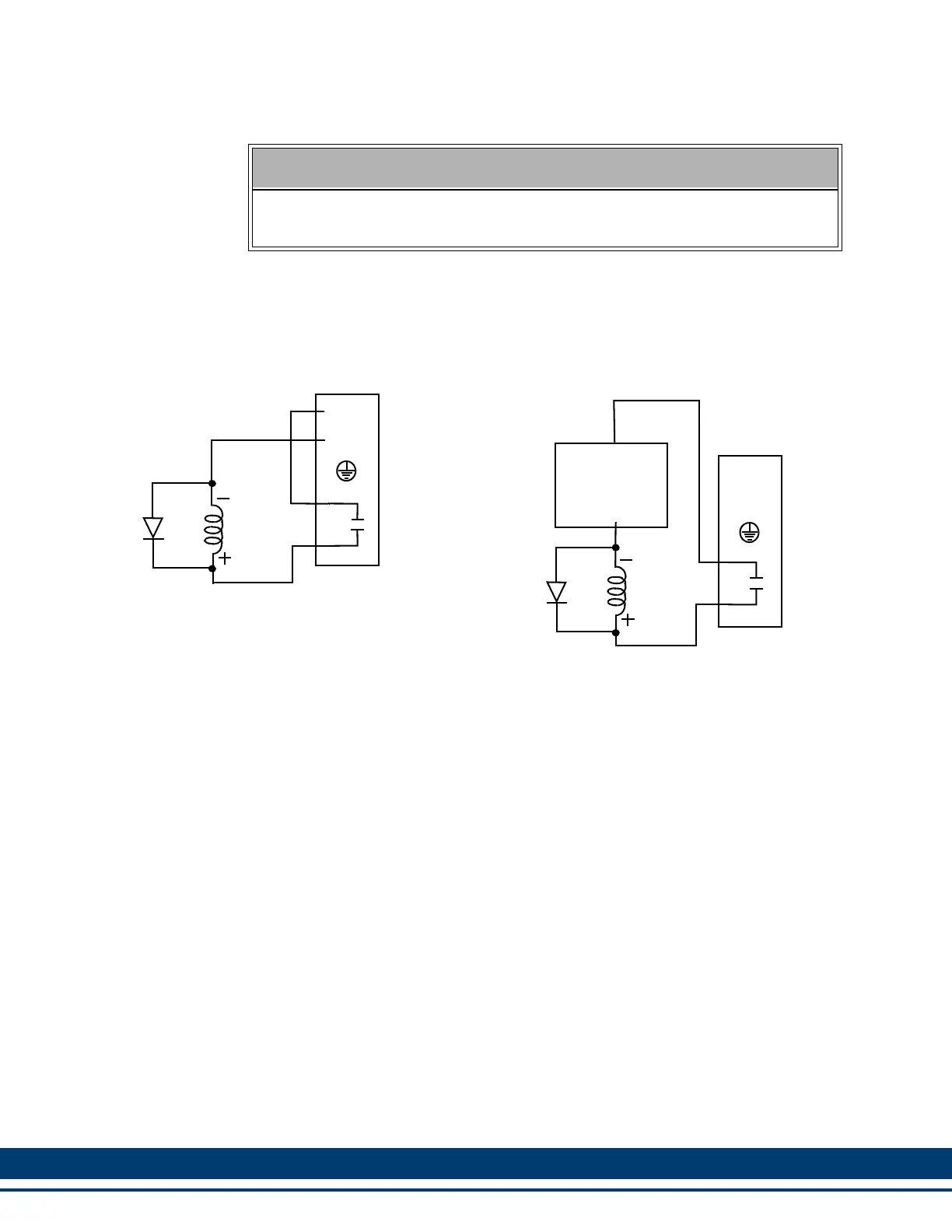
Figure 5-7: BR+ and BR- Wiring Examples
5.2.1.1 "EN" requirements and Safe-off Operation
The 230V Three Phase Drive is available either with Safe-off (-DSO, -DNSO), or
without Safe-off (-D, -DN). Regardless, the "EN" pin located on the 6-pin
connector must have 24Vdc applied to it in order for the drive to operate.
The following two sections describe the behavior of Safe-off Drives and non-Safe-off
Drives.
5.2.1.1.1 "EN" Operation on Safe-off Drives
If the Drive includes the Safe-off feature, the Drive will only perform a Safe-off fault if
the following two conditions are met:
• The drive is enabled by the application
• The "EN" input pin is not at 24Vdc
The general sequence of operation of a Safe-off Drive is as follows:
1. An external user-supplied circuit provides 24Vdc to the "EN" input
2. The drive is enabled via the Application Program
3. The application controls the motor as desired
4. The drive is disabled via the Application Program
5. The external user-supplied circuit removes 24Vdc from the "EN" input
NOTE
Use of a diode (as shown) or an external RC type snubber is highly recom-
mended for use with inductive loads, especially DC inductive loads.
Using 24V Power Source
+24V
COM
BR+
BR-
Using External Power Source
Brake
+24V
COM
Brake
External
Power
Supply
COM
BR+
BR-
1N4004
1N4004
 Loading...