Kollmorgen - December 2011 75
MMC Smart Drive Hardware Manual - 230V 1/3 PHASE MMC SMART DRIVE
5.1.3 PiCPro Port (Analog Drives)
This section details the PiCPro Port connector on the Analog Interfaced Drives (not -D
or -DN). For information on the PiCPro Port connector on Digital Interfaced Drives,
see section 5.1.2 on page 73.
The 9-pin male D-sub PiCPro Port connector (labeled “P1” on the front of the Drive)
provides serial communication for the PiCPro programming interface.
• Pin descriptions for are provided in Table 5-5
• Pin assignments are provided in Table 5-6
• The available PiCPro Port to PC cable is described in Table 5-7
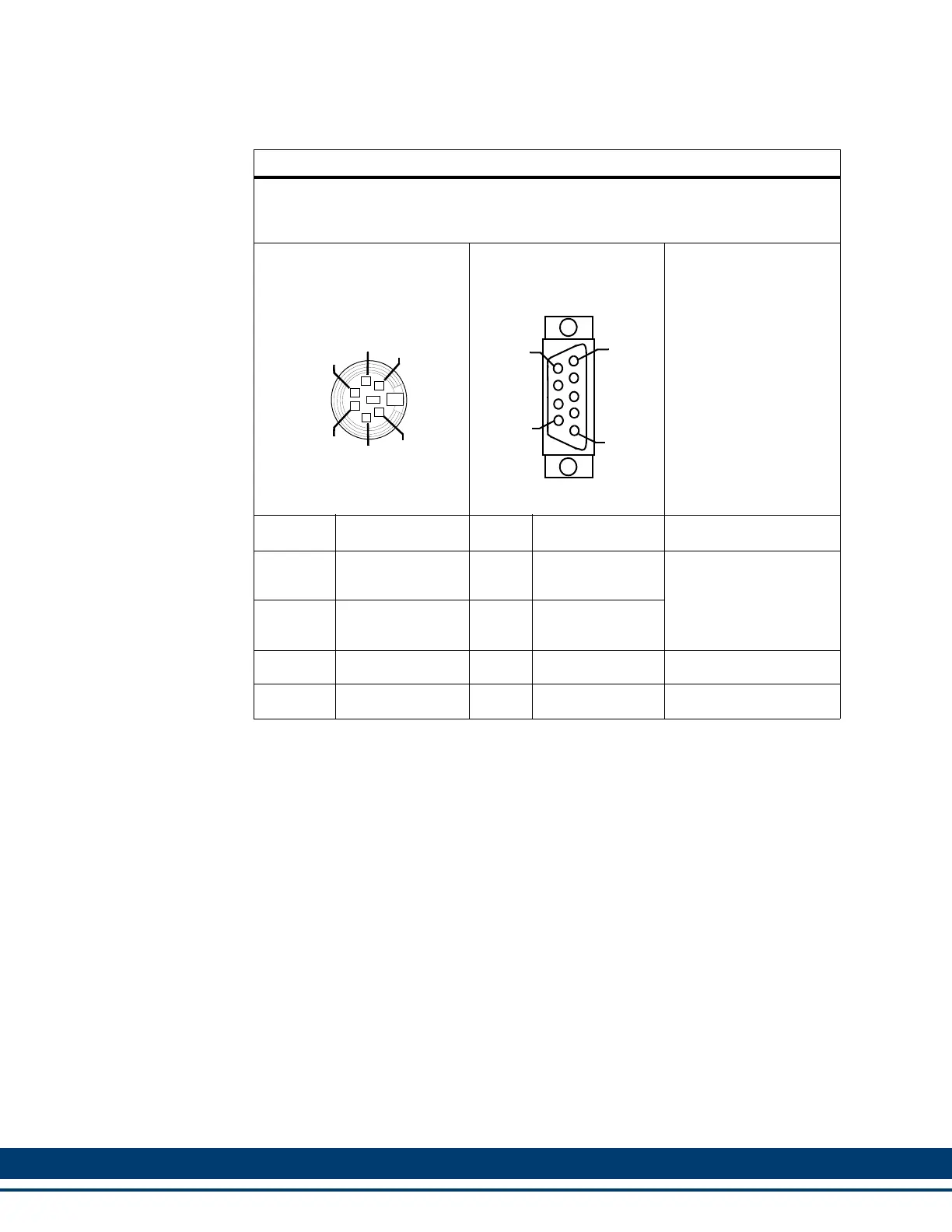
Table 5-4: PiCPr0 Port to PC Cable
Part Number: M.1302.8284
Length: 4 M (13 ft)
Cable type: 24 AWG, shielded, twisted pair, 4 conductor.
6-Pin male Miniature
Circular DIN (to PiCPro Port,
face view)
9-Pin female D-sub (to
PC COM Port, face view)
Pin Signal Pin Signal Notes
1
RS232 Receive
Data
3
RS232 Trans-
mit Data
Twisted
Pair
2
RS232 Transmit
Data
2
RS232 Receive
Data
5 Signal Ground 5 Signal Ground
Shell Drain Shell Drain
2
5
6
1
4
3
6
5
9
1
 Loading...