Kollmorgen - December 2011 287
MMC Smart Drive Hardware Manual - DRIVE RESIDENT DIGITAL MMC CONTROL
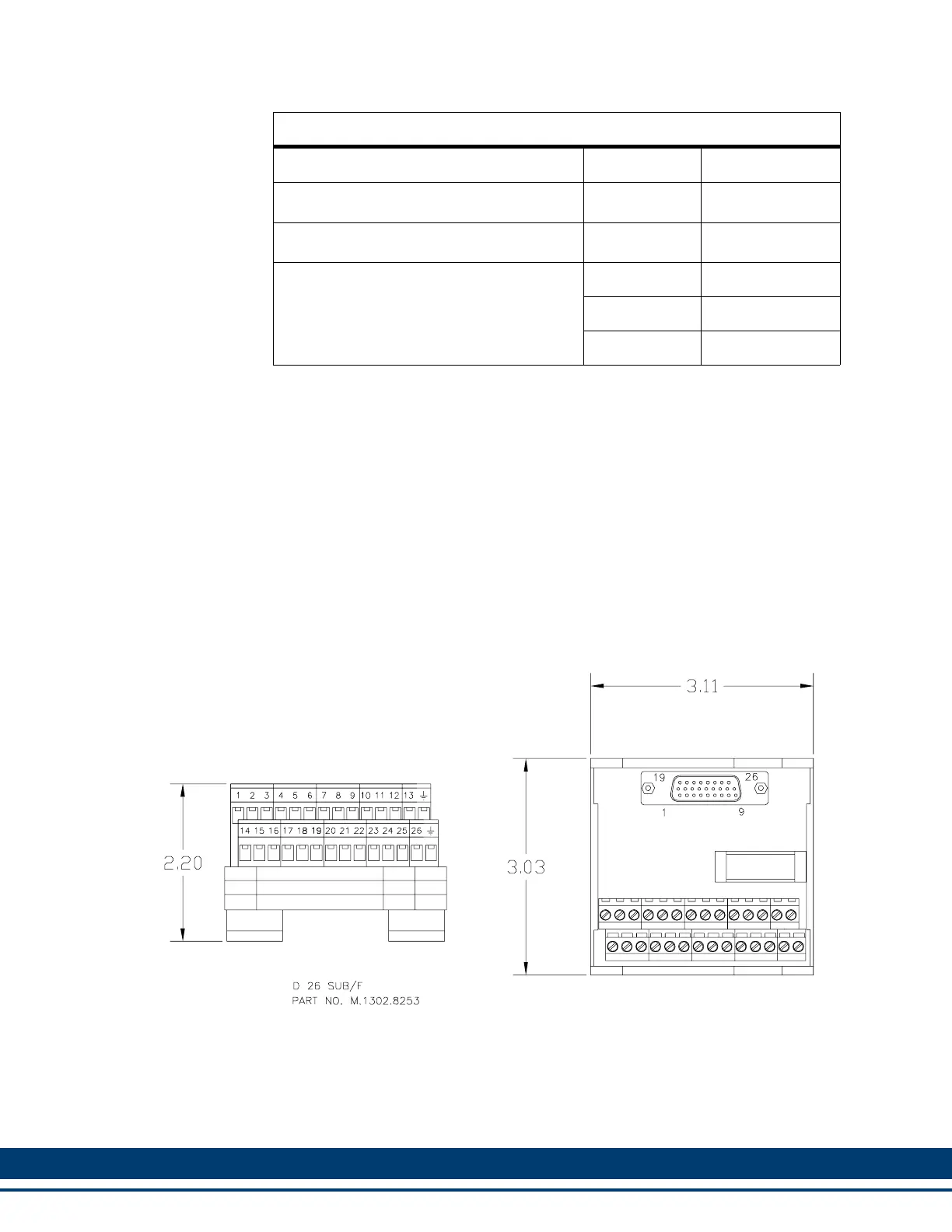
Figure 12-5: General I/O Port Breakout Box Dimensions
Table 12-20: General I/O Port Breakout Box and Cables
a
Description Length Part Number
DR Control Gen I/O Breakout Board
b
N/A M.1302.8480
DR Control Gen I/O Breakout Box
c
N/A M.1302.8253
DR Control Gen I/O & Aux I/O Connector to
Breakout Box Cable
1 M (3.3 ft) M.1302.8254
3 M (9.8 ft) M.1302.8255
9 M (29.5 ft) M.1302.8256
a. The connector pins marked with the “ground” symbol on the screw connector
are connected to the “D” connector shell for shield grounding purposes.
b. The Breakout Board is mounted directly to the General I/O connector, and
provides screw terminals wire termination.
c. The Breakout Box (see Figure 12-5 on page 287) is DIN-rail mounted, and
provides screw terminal wire termination. Use one of the cables listed in the
table to connect between the General I/O connector and the Breakout Box.
 Loading...