72 Kollmorgen - December 2011
MMC Smart Drive Hardware Manual - 230V 1/3 PHASE MMC SMART DRIVE
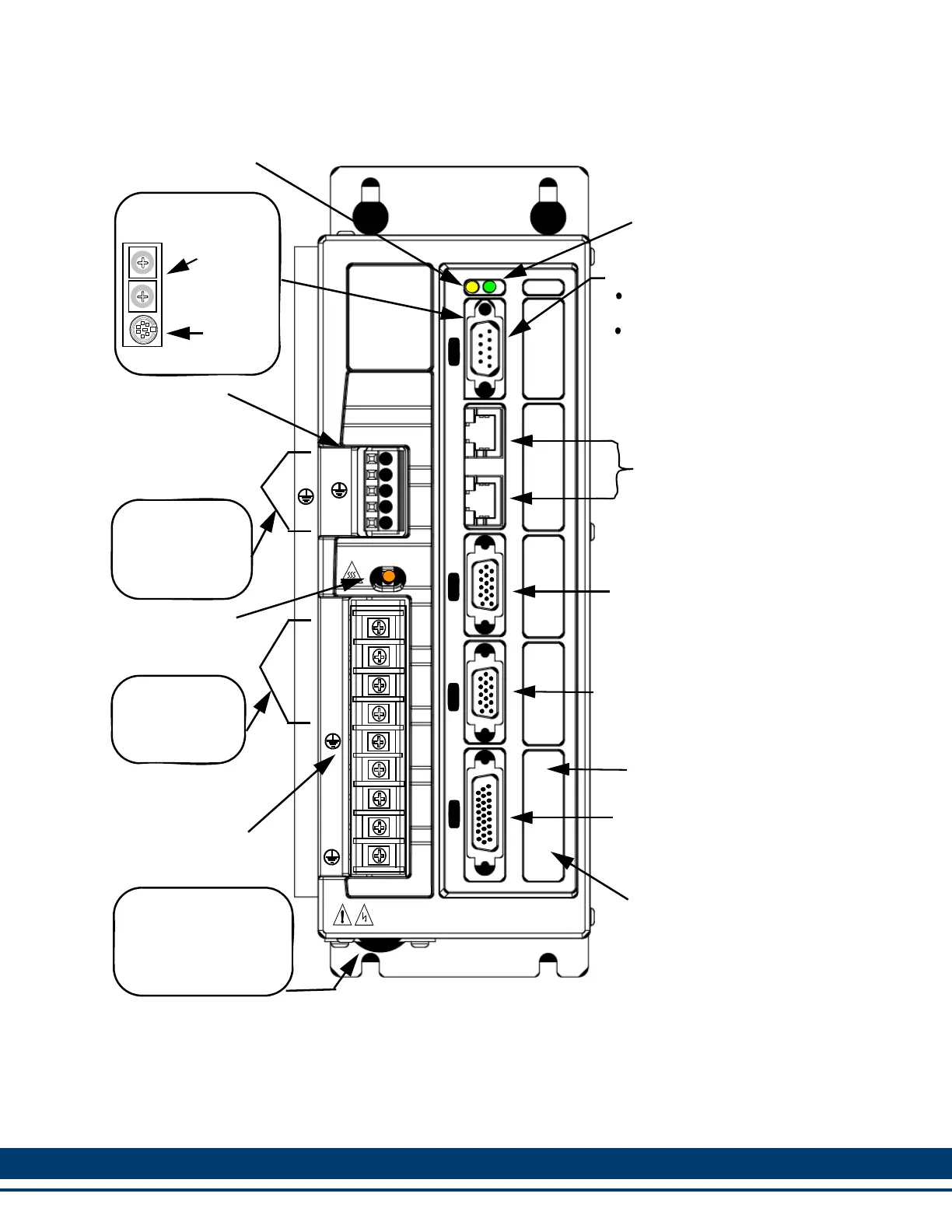
Figure 5-1: Front Panel, 230V Drives
+24V
COM
BR+
BR-
Feedback Connector (F1)
Drive I/O Connector (IO)
(26-Pin High Density D-Shell)
CAUTION - Risk of Electric Shock
High Voltage may exist up to 10 minutes after removing power
PiCPro Port (P1)
Line Power/
DC BUS
Motor Terminal Strip
9-Pin Standard D-Shell on
(15-Pin High Density D-Shell)
(9-Position Screw
Terminal Strip)
W
V
U
L2
L1
B-
B+
P
1
I
N
O
U
T
F
1
F
2
I
O
D1
P
Digital Link Connectors
(Digital Interfaced MMC-SD
1
2
3
4
8
7
6
5
9
0
1
2
3
4
8
7
6
5
9
0
Node
Address
Rotary
PiCPro
Digital Interfaced
Connector
Miniature Circular on
Digital Interfaced MMC-SD
Analog Interfaced MMC-SD
only)
Switches
(RJ45)
MMC-SD Only
Feedback Connector (F2)
(15-Pin High Density D-Shell)
(Digital Interfaced MMC-SD Only)
This section not on
Narrow Drive
Status LED (D1)
(Yellow)
Power LED (P)
(Green)
This section not on
Narrow Drive
(Single Phase Drive
Shown)
(4-Position Pluggable
Screw Terminal Strip)
Three Phase
Drive Only
NC
L1
L2
L3
Three Phase
Drive Only
+24V
COM
EN
BR+
BR-
(6-Position Cage-
Clamp Terminal
Three Phase
Drive Only
24VDC IN/Brake
Terminal Strip
(5-Position Screw
Terminal Strip)
Bus Voltage LED
(DC BUS)
(Orange)
(Single Phase Drive
Shown)
DC Bus/Regen
Terminal Strip
Strip)
 Loading...