Kollmorgen - December 2011 141
MMC Smart Drive Hardware Manual - 460V 3 PHASE MMC SMART DRIVE NEXTGEN
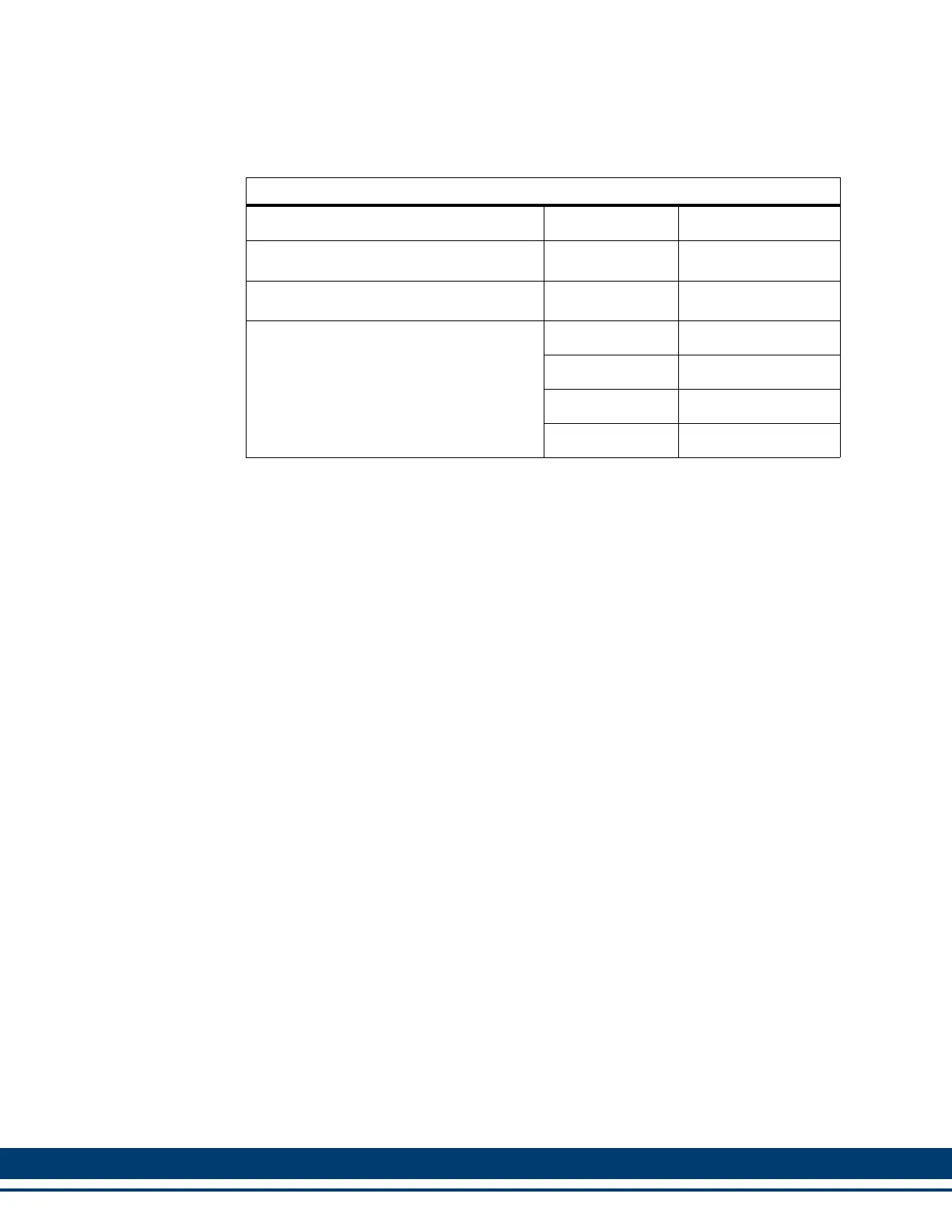
Table 6-10: Feedback Ports (F1 and F2) Breakout Box and Cables
Description Length Part Number
Drive F1/F2 Port Breakout Board
a
a. The Breakout Board (see Figure 6-3 on page 142) is mounted directly to the F1
and/or F2 connector, and provides screw terminal wire termination. Any combina-
tion of breakout board and feedback cable can be used on F1/F2, except a feed-
back cable on F1 and a breakout board on F2.
N/A M.1302.6970
Drive F1/F2 Port Breakout Box
b
b. The Breakout Box (see Figure 6-2 on page 142) is DIN-rail mounted, and pro-
vides screw terminal wire termination. Use one of the cables listed in the table to
connect between the F1 and/or F2 connector and the Breakout Box.
N/A M.1302.6972
MMC-SDN F1/F2 Port to Breakout Box
Cable
1 M (3.3 ft) M.3000.1330
3 M (9.8 ft) M.3000.1331
6 M (19.7 ft) M.3000.1332
9 M (29.5 ft) M.3000.1333
 Loading...