134 Kollmorgen - December 2011
MMC Smart Drive Hardware Manual - 460V 3 PHASE MMC SMART DRIVE NEXTGEN
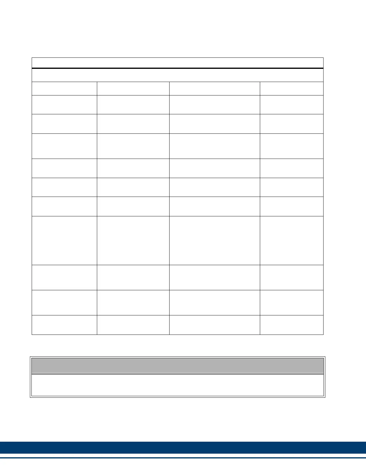
Table 6-4: Pin Description for Feedback Connector (F1)
F1 Feedback Signals
Signal Type Signal Name Notes Pin
Incremental Encoder
Inputs
A1, A1/, B1, B1/, I1, I1/
Differential A quad B encoder
signals.
12, 13, 14, 15, 6, 7
Sinewave Encoder In-
puts
Sin, Sin/, Cos, Cos/ Sinewave Encoder signals 12, 13, 14, 15
Sinewave Encoder
Data Channel In/Out
RS-485 Data +, RS-485
Data -, RS-485 Clock+,
RS-485 Clock-
RS-485 signals for connecting
the Sinewave Encoder Data
Channel to the drive
6, 7, 2, 3
SFD Communication
Channel (future)
Com+, Com- SFD communication signals 6, 7
Resolver Inputs Sin+, Sin-, Cos+, Cos-
Resolver stator feedback sig-
nals
12, 13, 14, 15
Resolver Outputs Carrier+, Carrier-
Resolver rotor excitation sig-
nals.
6, 7
Temperature Input Temperature
Thermostat (normally- closed)
or Thermistor (Phillips KTY84-
130 PTC or equivalent recom-
mended) input for detecting
over temperature conditions
within the motor. These inputs
are shared with F2.
8, 9
+5V Encoder Power
Outputs
+5V Source
Regulated +5VDC for powering
the attached encoder (350ma
max).
10
+5V Encoder Power
Sense Lines
+5V Sense+, +5V
Sense-
These signals should be tied to
the +5V power and ground lines
at the encoder.
4, 5
Signal and Power
Common
Common
Return path for feedback sig-
nals and +5V power output
11
PROVIDING 8VDC ENCODER POWER
Some Encoders, specifically the Stegmann Hiperface, require 8VDC power to operate. 8VDC Power
can be provided on pins 10 and 11 by connecting the +5V Sense Lines (pins 4 & 5) together.
 Loading...