Kollmorgen - December 2011 135
MMC Smart Drive Hardware Manual - 460V 3 PHASE MMC SMART DRIVE NEXTGEN
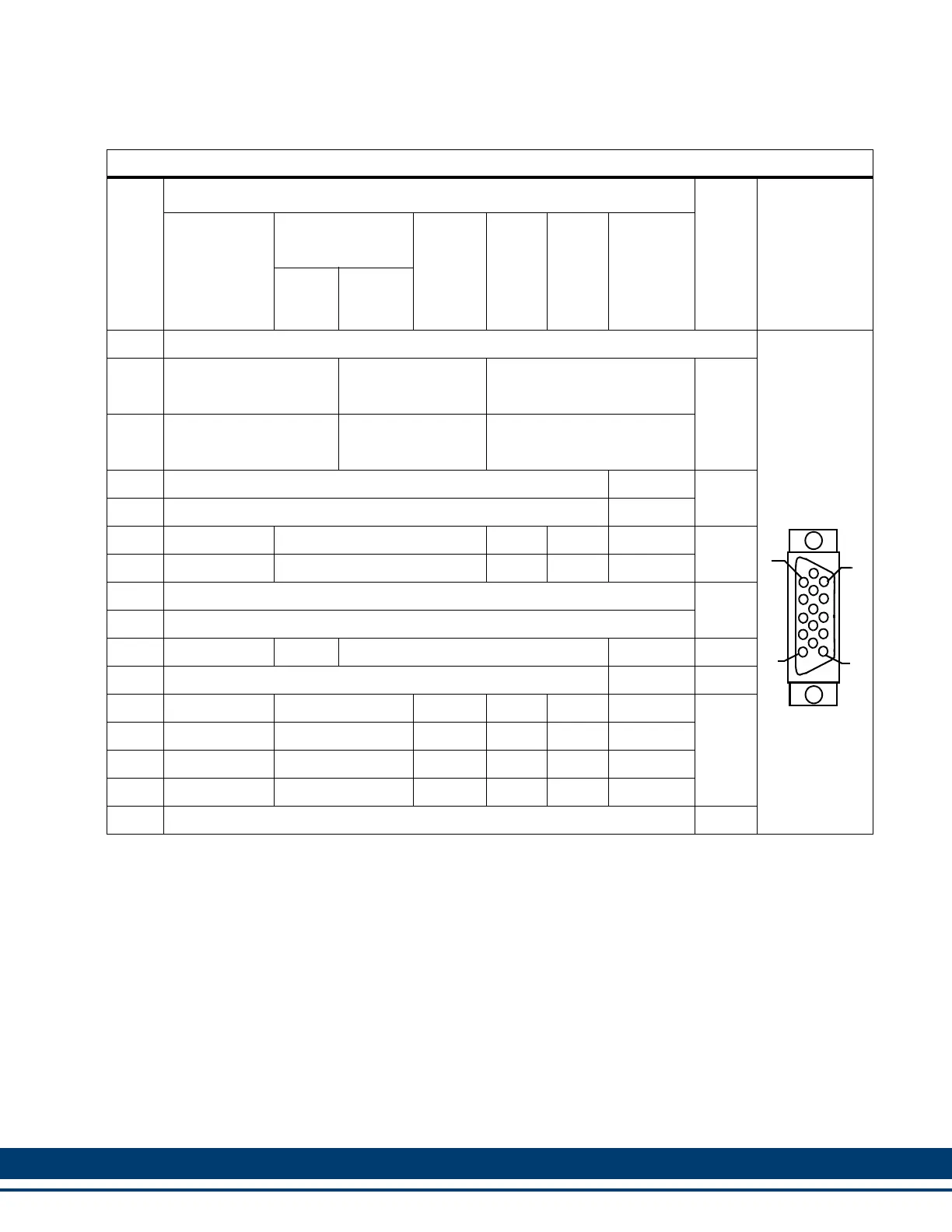
Table 6-5: Pin Assignments for Feedback Connector (F1)
Pin
Feedback Device
In/
Out
Connector
Pinout
Digital
Incremental
Encoder
Sinewave
Encoder
BISS
a
a. Supports BiSS Mode B (digital)
1V
p-p
Sine
Wave
SFD
b
b. SFD (future release)
Resolver
Hiper-
face
c
c. Stegmann Hiperface
Endat
d
d. Supports Endat 1.1 (Support for Endat 2.1 & 2.2 in future release)
1 N/U (Not Used)
15-pin
Female
HD D-Sub
2 N/U
RS-485
Clock+
N/U
Out
3 N/U
RS-485
Clock-
N/U
4
+5V Sense+
e
e. Use of Sense Lines is optional, except if connecting to a Hiperface encoder (see footnote
(h)
, below)
N/U
In
5
+5V Sense-
e
N/U
6 I1 RS-485 Data+ N/U Com+ Carrier+
Note
f
f. Pins 6 and 7 are In/Out for Hiperface, Endat, and SFD; Inputs for Digital Incremental and BiSS; and Out-
puts for Resolver
7 I1/ RS-485 Data- N/U Com- Carrier-
8
Temperature+
g
g. Temperature inputs (pins 8 and 9) are shared with the F2 connector
In
9
Temperature-
g
10 +5V Source
+8V
h
h. Hiperface requires +8Vdc. To supply +8V from pin 10, connect +5V Sense lines (pins 4 & 5) together.
+5V Source N/U Out
11 Common N/U In/Out
12 A1 Sine N/U Sine N/U Sin+
In
13 A1/ Sine/ N/U Sine/ N/U Sin-
14 B1 Cos N/U Cos N/U Cos+
15 B1/ Cos/ N/U Cos/ N/U Cos-
Shell Shield N/A
5
1
15
11
 Loading...