106 Kollmorgen - December 2011
MMC Smart Drive Hardware Manual - 230V 1/3 PHASE MMC SMART DRIVE
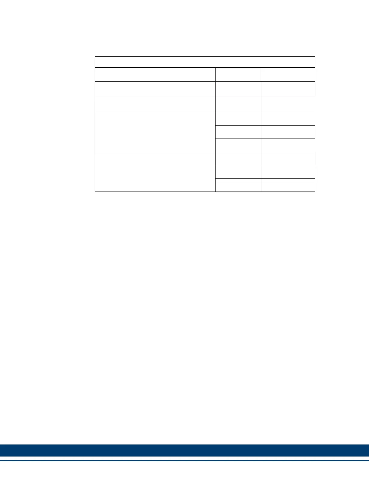
Table 5-34: Drive I/O Port Breakout Box and Cables
Description Length Part Number
Drive I/O Port Breakout Board
a
a. The Drive I/O Breakout Board (see Figure 5-5 on page 107) is mounted
directly to the IO connector, and provides screw terminals wire termination.
N/A M.1302.6971
Drive I/O Breakout Box
b
b. The Drive I/O Breakout Box (see Figure 5-4 on page 107) is DIN-rail
mounted, and provides screw terminal wire termination. Use one of the
cables listed in the table to connect between the IO connector and the Break-
out Box.
N/A M.1302.6973
Drive I/O Port to Breakout Box Cable
1 M (3.3 ft) M.1302.6982
3 M (9.8 ft) M.1302.6984
9 M (29.5 ft) M.1302.6985
Drive I/O Port Breakout Box and Cable
Kits. These kits include an M.1302.6973
Breakout Box and an interconnect cable of
the indicated length.
1 M (3.3 ft) M.1302.7009
3 M (9.8 ft) M.1302.7030
9 M (29.5 ft) M.1302.7031
 Loading...