232 Kollmorgen - December 2011
MMC Smart Drive Hardware Manual - S200-DLS DRIVE
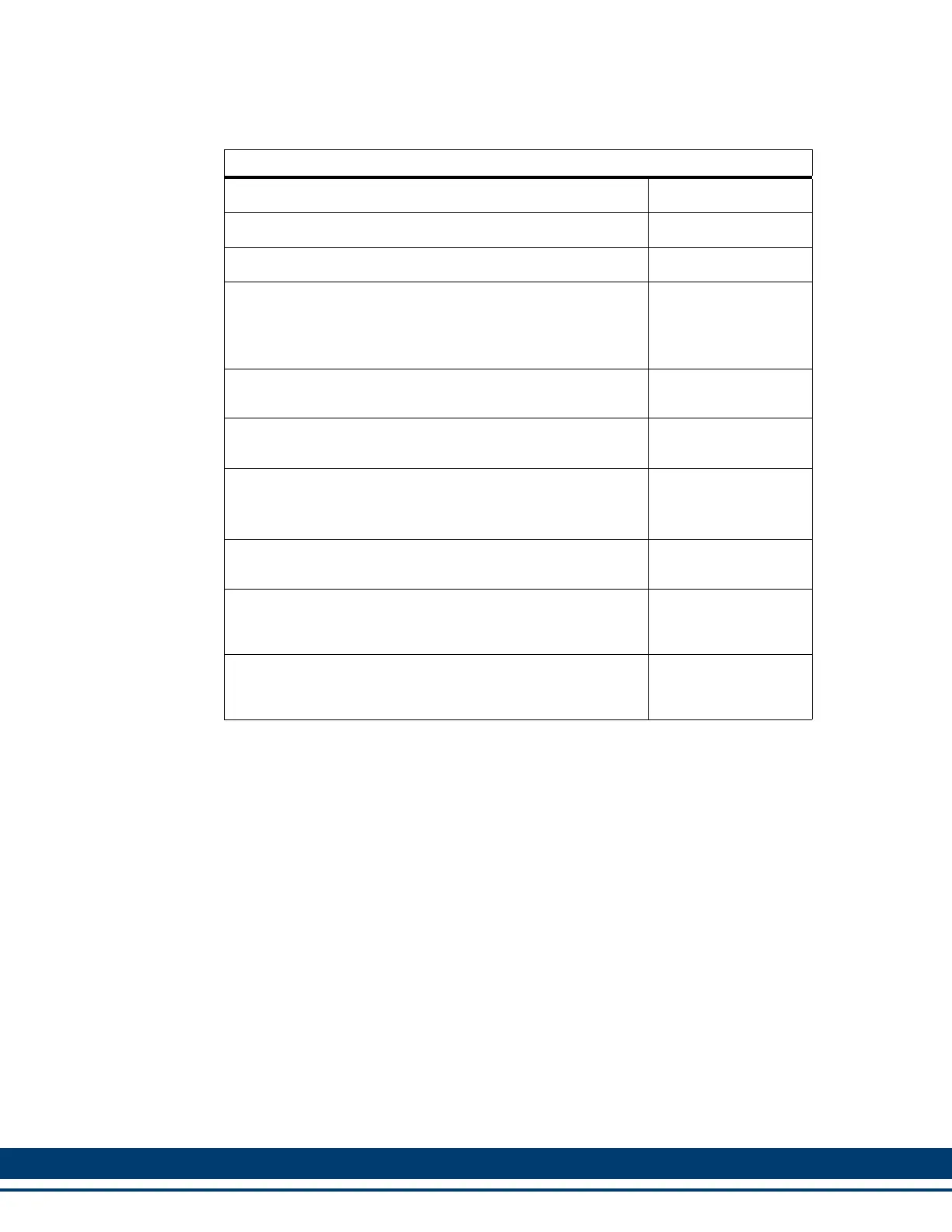
Table 8-16: Power Section Wiring Accessories
Description Part Number
Command I/O (J4) Drive-mounted Breakout Board M.1302.6971
Command I/O (J4) Panel-mounted Breakout Box M.1302.6973
Command I/O (J4) to Breakout Box cables:
3.3ft (1M)
9.8ft (3M)
29.5ft (9M)
M.1302.6982
M.1302.6984
M.1302.6985
AC Power (J1, 1.5A, 3A, and 6A S200-DLS drives only)
9-pin screw terminal
767-009903-01
Ctrl Power (J1, 12A, 24A, and DC S200-DLS drives only)
3-pin screw terminal
767-003907-01
Motor Power (J2, 1.5A, 3A, 6A, and DC S200-DLS drives
only
a
)
4-pin screw terminal
a. J2 is not present on the 12A and 24A S200-DLS drives. Connection for Motor
Power is provided via a non-pluggable screw-terminal connector.
767-004908-01
Feedback (J3)
6-pin, solder terminal
749-139401-01
Kit containing one each of connector J1 (P/N 767-003907-
01, as described above), plus J6 and J7 (as described in
Table 8-15 on page 229)
M.3000.0727
Kit containing one each of connector J1 (P/N 767-009903-
01, as described above), plus J6 and J7 (as described in
Table 8-15 on page 229)
M.3000.0728
 Loading...