264 Kollmorgen - December 2011
MMC Smart Drive Hardware Manual - DRIVE RESIDENT DIGITAL MMC CONTROL
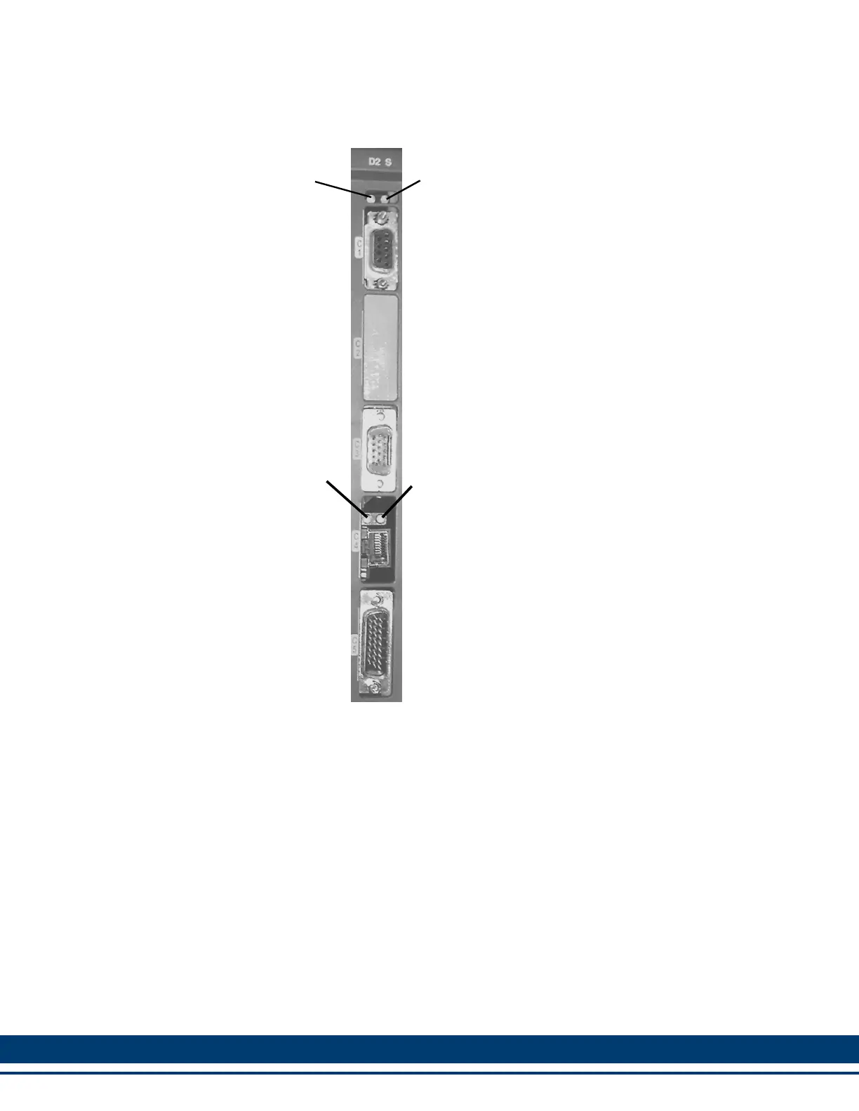
Figure 12-1: The Drive Resident Digital MMC Control
* The Block I/O Port connector (C1), Ethernet Communications Port connector (C4), Ethernet Link
LED, and Ethernet Activity LED are present on the Digital MMC-D1 Control, but are not functional.
Diagnostic LED (D2)
(Yellow)
User Serial Port (C3)
(15-Pin High Density D-Shell)
Block I/O Port (C1)*
(9-Pin Standard D-Shell)
Scan LED (S)
(Green)
Ethernet Communications Port (C4)*
(RJ-45 8-Pin)
General I/O Port (C5)
(26-Pin High Density D-Shell)
Ethernet Activity LED*
(Green)
Ethernet Link LED*
(Green)
 Loading...