Kollmorgen - December 2011 293
MMC Smart Drive Hardware Manual - DRIVE RESIDENT DIGITAL MMC CONTROL
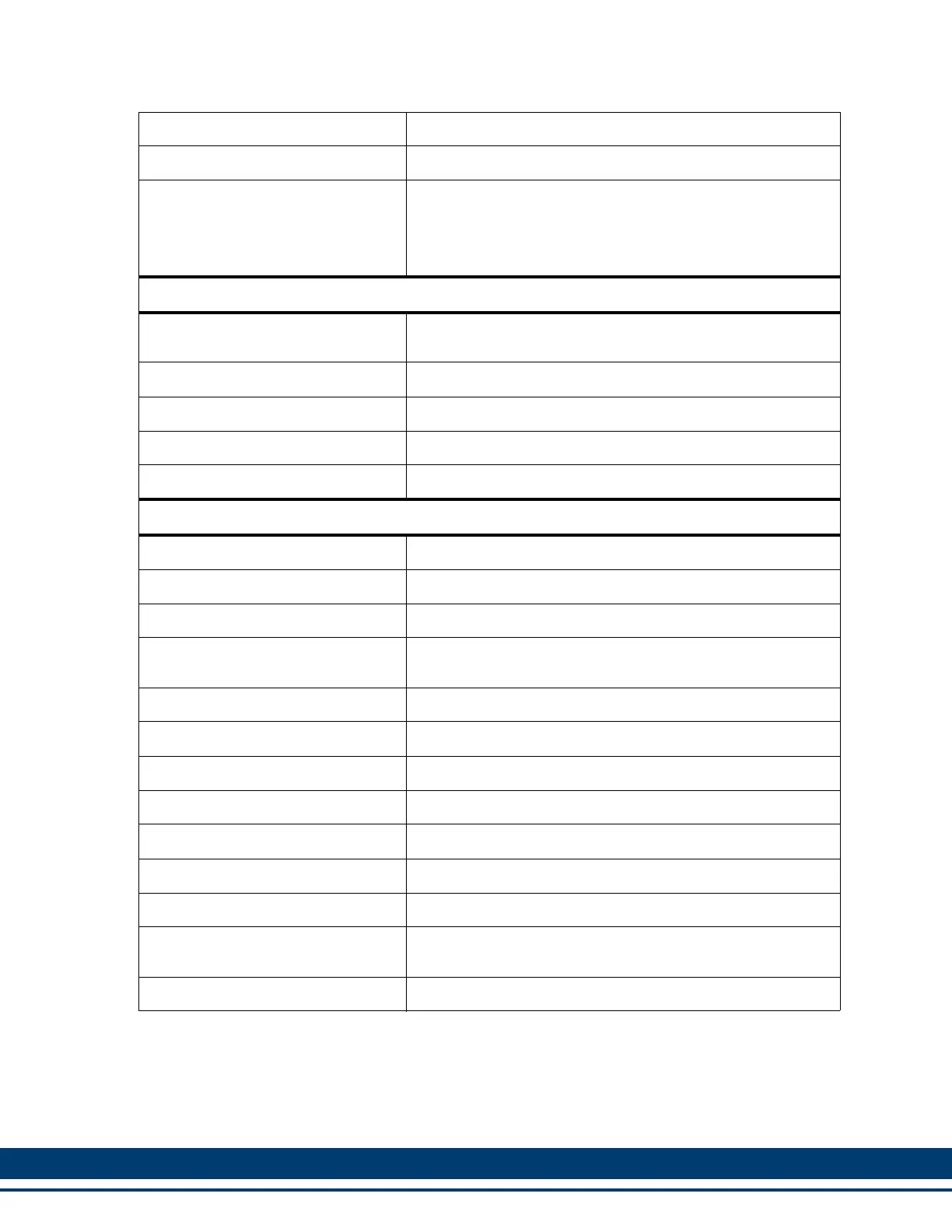
Input voltage from MMC-SD Drive 20 VDC to 30 VDC
Input power from MMC-SD Drive 250 mA
Time-of-day clock
Clock tolerance
Access via PiCPro 10.2 and above or your application pro-
gram
At 25°C (77°F),±1 second per day
Over temperature, voltage and aging variation,
+2/-12 seconds per day
General DC Inputs
Configuration
Sourcing only. Operates with IEC Type 1 inputs (per IEC
1131-2)
Input voltage Nominal 24 VDC, maximum 30 VDC
Guaranteed on voltage 15 VDC
Guaranteed off voltage 5 VDC
Turn on/off time 1 ms
General DC Outputs
Number of outputs 8 outputs
Input voltage Nominal 24 VDC, 30 VDC maximum
Configuration Eight solid-state switches.
Protection of logic circuits
Optical isolation between the logic and field side, transient
suppression on the 24V external supply
Maximum current .25 A per output
Voltage range 24 VDC nominal, 5 to 30 VDC
Switch characteristics Solid-state switches
Time delay on for resistive loads 50 µsec max
Time delay off for resistive loads 50 µsec max
Leakage current in off state 0.5 mA max
Switch voltage, maximum ON 1 VDC max
Short circuit protection for each
group
15 A (max) pulses for about 130 µsec every 100 msec until
short is removed
Scan loss response Outputs turn off
 Loading...