Kollmorgen - December 2011 29
MMC Smart Drive Hardware Manual - INSTALLING THE MMC SMART DRIVE
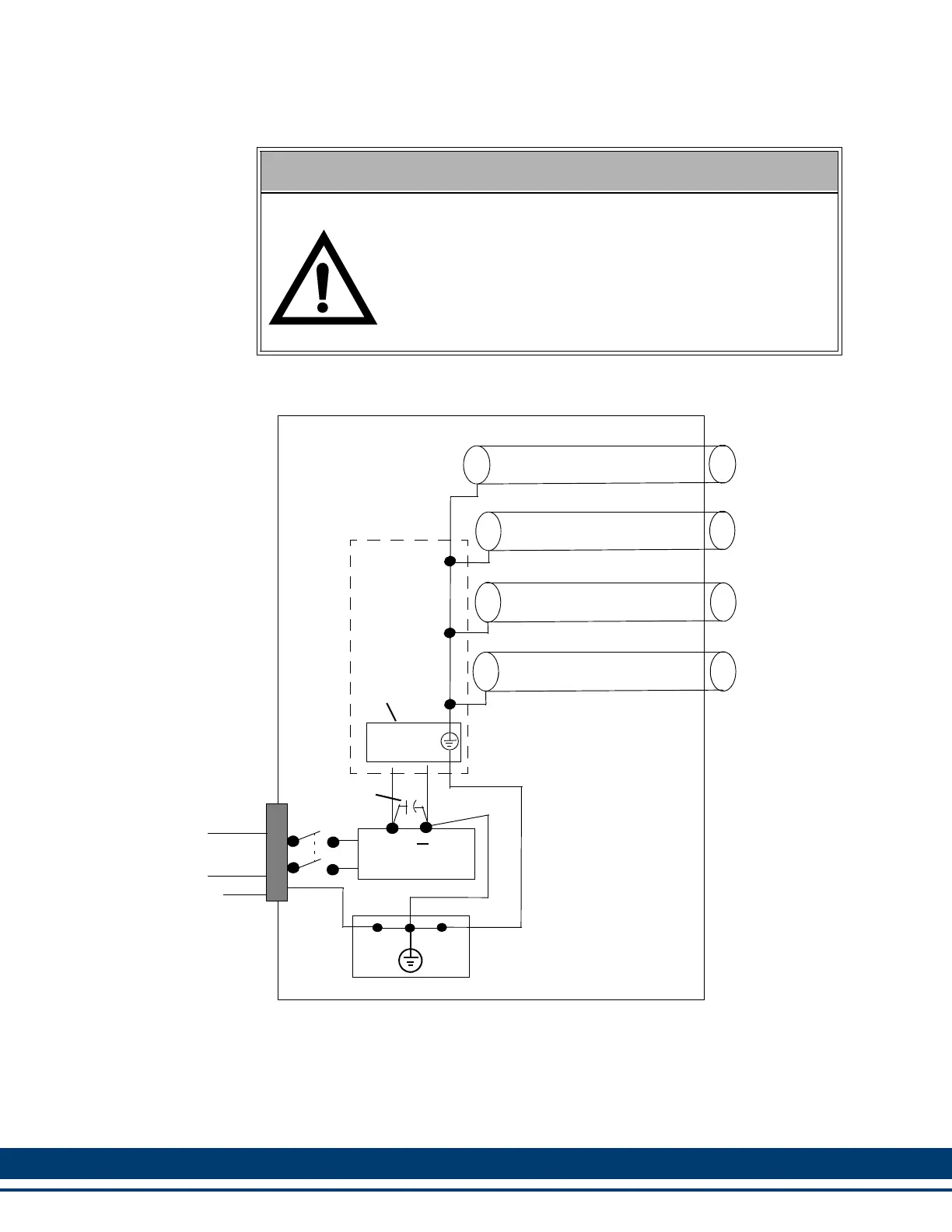
Figure 3-2: Recommended Signal Separation
To prevent excessive conducted emissions from a DC power source (typically 24V)
used for digital I/O, a .001 micro farad capacitor should be used. Connect the
capacitor from the +24V DC to COMMON at the distribution terminals.
WARNING: FEEDBACK DEVICE DAMAGE
Feedback Cable Installation and Removal
All power to the Smart Drive (24 Vdc and main AC power) must
be removed before connecting/disconnecting feedback cable
connectors at the Smart Drive (F1 and F2 connector) or at the
motor feedback device. Also, all connections must be secure
when power is applied. Failure to follow these precautions may
result in damage to the feedback device or Smart Drive.
MMC
PICPRO COMMUNICATIONS CABLE
MOTOR POWER CABLE
Drive I/O CABLE
24V
COM
INCOMING
AC POWER
GND
SINGLE-POINT GROUND
SINGLE-POINT GROUND
DC POWER SUPPLY
+
Power
Connector
Capacitor
Smart
Drive
MOTOR FEEDBACK CABLE
(MAINS)
SINGLE POINT GROUND (SPG)
(.001 uF)
 Loading...