8 Commissioning/Shutdown
125 of 212
PumpDrive 2
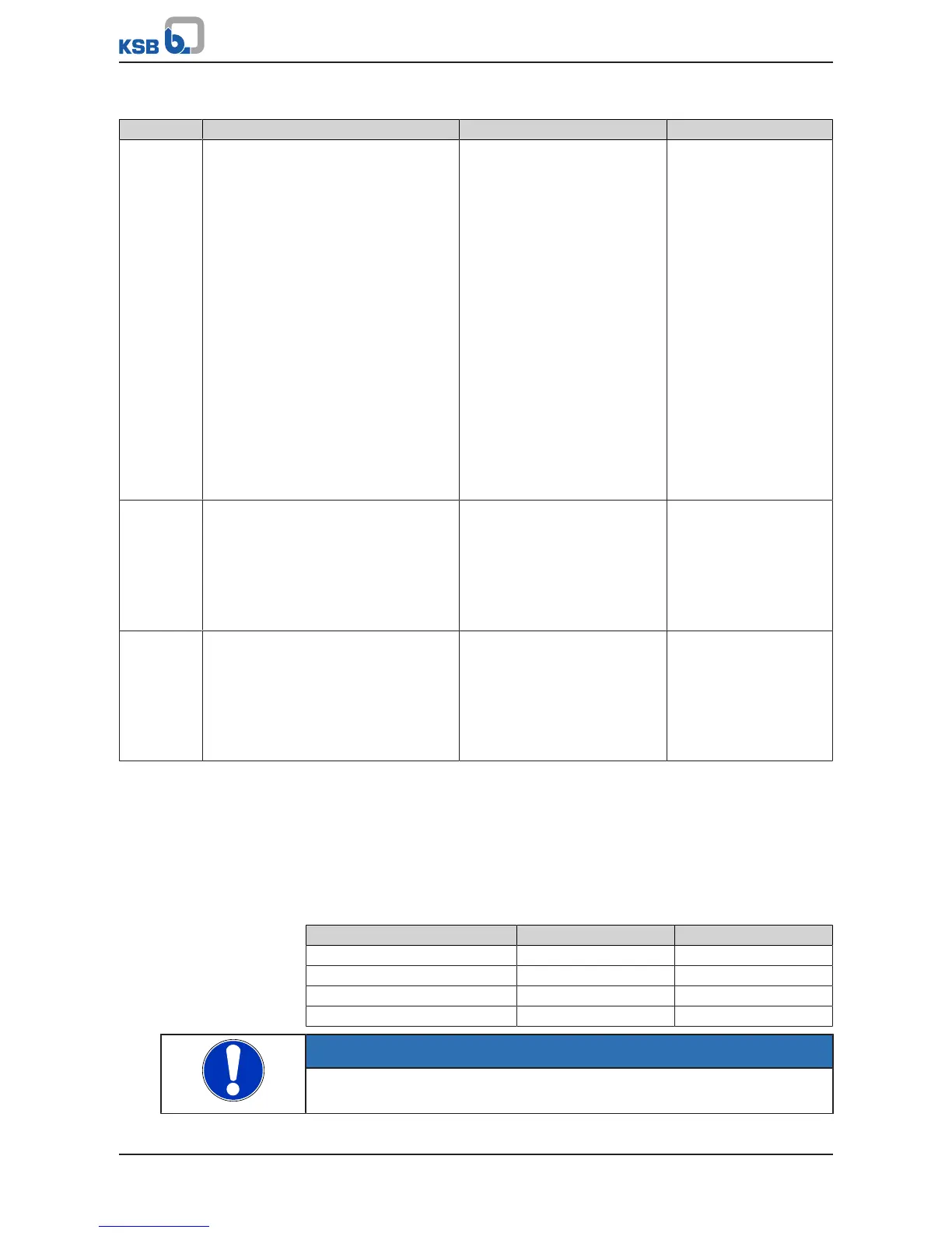
Table99: Relay 3 to 8 parameters
Parameter Description Possible settings Factory setting
3-8-11-1
3-8-12-1
3-8-13-1
3-8-14-1
3-8-15-1
3-8-16-1
Relay 3 Function
Relay 4 Function
Relay 5 Function
Relay 6 Function
Relay 7 Function
Relay 8 Function
Selectable messages via relays 3 to 8
▪ None
▪ AUTO operating mode
▪ RUN operating status
▪ AUTO/SLEEP operating
status
▪ Warning
▪ Alert
▪ Alert or Warning
▪ Dynamic overload
protection
▪ Current too high
▪ Current too low
▪ Frequency too high
▪ Frequency too low
Power too high
▪ Power too low
▪ Actual value = setpoint
None
3-8-11-2
3-8-12-2
3-8-13-2
3-8-14-2
3-8-15-2
3-8-16-2
Time Delay ON
Period of time during which the event
selected must be continually available until
the relay is set
0,0 – 10,0 s 0,5 s
3-8-11-3
3-8-12-3
3-8-13-3
3-8-14-3
3-8-15-3
3-8-16-3
Time Delay OFF
Period of time for which the event selected
must have gone before the relay is reset
0,0 – 10,0s 0,5 s
Analog inputs on the I/O extension board
By default, the value selected via parameter 3-8-8-1 (Assignment 1, Analog Output 2)
is output as a 4 - 20mA signal at the analog output. Four different process values can
be assigned to the analog output. The selection as to which value is output is made
via two digital inputs on the IO extension board (2bits = 4options). For this purpose,
parameterise the function of the digital inputs to Control AOUT Bit 0 or Control
AOUT Bit 1. (ðSection8.10.4,Page122)
Table100: Controlling the output values
Assignment at analog output 1 Control AOUT Bit 1 Control AOUT Bit 0
1 0 0
2 0 1
3 1 0
4 1 1
NOTE
Only the digital inputs on the I/O extension board can be used to initiate the
measurement value output sequence for analog output2.