1-S67
MX5100, WSM
ENGINE
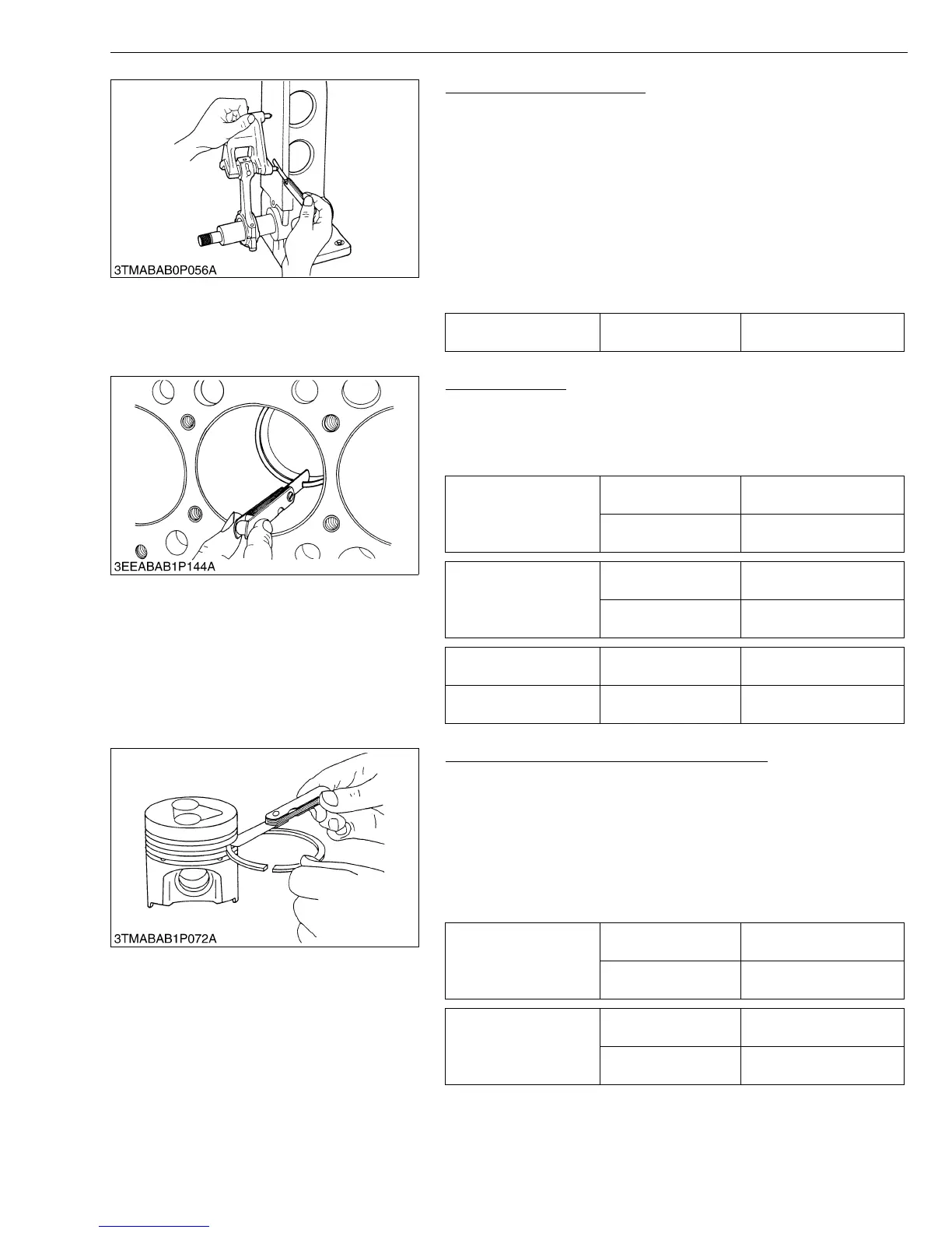
Connecting Rod Alignment
• Since the I.D. of the connecting rod small end bushing is the
basis of this check, check bushing for wear beforehand.
1. Install the piston pin into the connecting rod.
2. Install the connecting rod on the connecting rod alignment tool.
3. Put a gauge over the piston pin, and move it against the face
plate.
4. If the gauge does not fit squarely against the face plate, measure
the space between the pin of the gauge and the face plate.
5. If the measurement exceeds the allowable limit, replace the
connecting rod.
W10314620
Piston Ring Gap
1. Insert the piston ring into the lower part of the liner (the least worn
out part) with the piston.
2. Measure the ring gap with a feeler gauge.
3. If the gap exceeds the allowable limit, replace the ring.
W1032246
Clearance between Piston Ring and Groove
1. Clean the rings and the ring grooves, and install each ring in its
groove.
2. Measure the clearance between the ring and the groove with a
feeler gauge or depth gauge.
3. If the clearance exceeds the allowable limit, replace the piston
ring.
4. If the clearance still exceeds the allowable limit with new ring,
replace the piston.
W1032489
Connecting rod
alignment
Allowable limit
0.05 mm
0.002 in.
Top ring
Factory spec.
0.20 to 0.35 mm
0.0079 to 0.013 in.
Allowable limit
1.25 mm
0.0492 in.
Second ring
Factory spec.
0.40 to 0.55 mm
0.016 to 0.021 in.
Allowable limit
1.25 mm
0.0492 in.
Oil ring Factory spec.
0.25 to 0.45 mm
0.0099 to 0.017 in.
Allowable limit
1.25 mm
0.0492 in.
Second ring
Factory spec.
0.0930 to 0.128 mm
0.00367 to 0.00503 in.
Allowable limit
0.20 mm
0.0079 in.
Oil ring
Factory spec.
0.020 to 0.060 mm
0.00079 to 0.0023 in.
Allowable limit
0.15 mm
0.0059 in.