2-M3
MX5100, WSM
CLUTCH
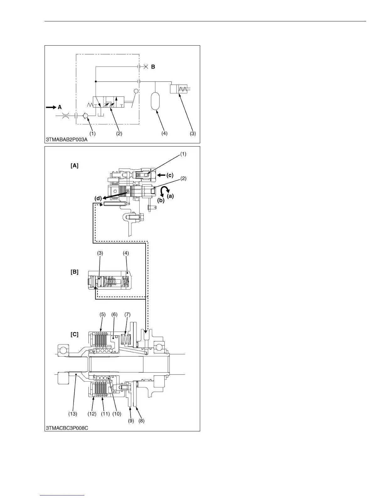
[3] OIL FLOW
The oil adjusted the pressure by the regulator valve
flows into the PTO clutch valve (2). When the PTO lever
is at the “DISENGAGED” position, the oil does not flow
through the PTO clutch valve (2) to the clutch pack.
When the PTO lever is at the “ENGAGED” position, the
oil flows through the PTO clutch valve (2) to the
accumulator (4) and the PTO clutch pack (3) to engage it.
W10132060
The oil from the regulator valve flows into the clutch
valve and opens the check valve (1). When the shift
lever is set at the “ENGAGED” position, the spool (2) is
turned to A position, then the oil flows through the spool
(2) into the accumulator and the clutch pack. Oil entering
the clutch pack pushes the piston (4) to engage the
clutch pack. The accumulator absorbs the engaging
shock of the clutch pack.
When the shift lever is set at the “DISENGAGED”
position, the spool (2) is turned to B position, then the oil
from the regulator valve is stopped by the spool (2) and
the oil in the PTO clutch pack and accumulator is drained
into the transmission case. Thus the piston (4) is pushed
back, the brake plate (7) is also moved to contact the
brake disc (6) so as to stop the rotation and the drag of
the PTO shaft.
W10133120
(1) Check Valve
(2) PTO Clutch Valve
(3) PTO Clutch Pack
(4) Accumulator
A : From Regulator Valve
B : PTO Clutch Operating
Pressure Check Port
(1) Check Valve
(2) Spool
(3) Accumulator Piston
(4) Bearing Case
(5) Plate
(6) Piston
(7) Brake Spring
(8) Brake Disc
(9) Brake Plate
(10) Return Spring
(11) Clutch Disc
(12) Back Plate
(13) Clutch Hub
(a) ENGAGED Position
(b) DISENGAGED Position
(c) From Regulator Valve
(d) Drain (To the Transmission
Case)
[A] PTO Clutch Valve
[B] Accumulator
[C] PTO Clutch Pack