5-S8
MX5100, WSM
BRAKES
[3] SERVICING
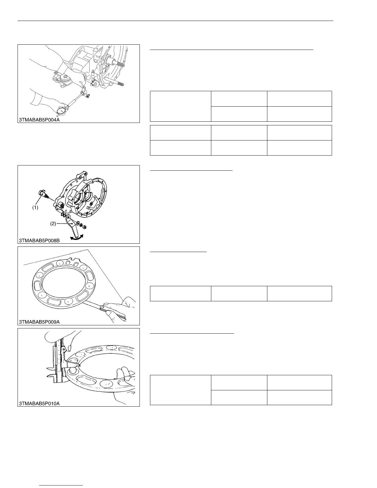
Clearance between Brake Lever Link Shaft and Bushing
1. Measure the brake lever link shaft O.D. with an outside
micrometer.
2. Measure the brake lever link bushing I.D. with a cylinder gauge.
3. Calculate the clearance.
4. If the clearance exceeds the allowable limit, replace the bushing.
W10118530
Brake Cam Lever Movement
1. Assemble the brake cam (1) and brake cam lever (2).
2. Move the brake cam lever by hand to check the movement.
3. If the movement is heavy, refine the brake cam lever or brake
case with sandpaper.
W10144750
Cam Plate Flatness
1. Place the cam plate on the surface plate.
2. Measure the flatness of cam plate with a feeler gauge at four
points on a diagonal line.
3. If the measurement exceed the allowable limit, replace it.
W10145650
Height of Cam Plate and Ball
1. Measure the dimension of the cam plate with the ball installed.
2. If the measurement is less than the allowable limit, replace the
cam plate and balls.
3. Inspect the ball holes of cam plate for uneven wear. If the uneven
wear is found, replace it.
W10147220
Clearance between
brake lever link shaft
and brake lever link
bushing
Factory spec.
0.125 to 0.195 mm
0.00492 to 0.00768 in.
Allowable limit
1.0 mm
0.039 in.
Brake lever link shaft
O.D.
Factory spec.
19.955 to 19.975 mm
0.78563 to 0.78642 in.
Brake lever link bushing
I.D.
Factory spec.
20.100 to 20.150 mm
0.79134 to 0.79331 in.
(1) Brake Cam (2) Brake Cam Lever
Cam Plate Flatness Allowable limit
0.3 mm
0.012 in.
Height of cam plate and
ball
Factory spec.
20.9 to 21.1 mm
0.823 to 0.831 in.
Allowable limit
20.5 mm
0.807 in.