9-S17
MX5100, WSM
ELECTRICAL SYSTEM
(6) Glow Control System
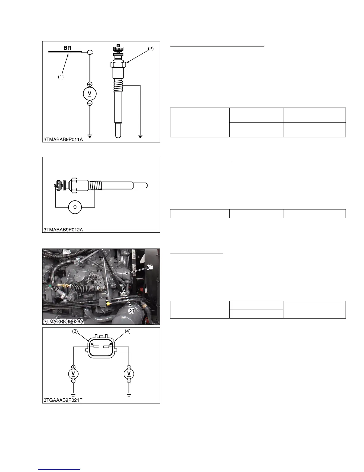
Glow Plug Lead Terminal Voltage
1. Disconnect the wiring lead (1) from the glow plug (2) after turning
the main switch off.
2. Turn the main switch key to the “PREHEAT” position, and
measure the voltage between the lead terminal and the chassis.
3. Turn the main switch key to the “START” position, and measure
the voltage between the lead terminal and the chassis.
4. If the voltage at either position differs from the battery voltage, the
wiring harness or main switch is faulty.
W1093015
Glow Plug Continuity
1. Disconnect the lead from the glow plugs.
2. Measure the resistance between the glow plug terminal and the
chassis.
3. If 0 ohm is indicated, the screw at the tip of the glow plug and the
housing are short-circuited.
4. If the factory specification is not indicated, the glow plug is faulty
W1093427
(7) Engine Stop Solenoid
Connector Voltage
1. Disconnect the 2P connector from engine stop solenoid.
2. Turn the main switch key to the "ON" position.
3. Measure the voltage between the terminal 1, terminal 2 and
body.
4. If the voltage differs from the battery voltage, the wiring harness
or main switch is faulty.
W1096779
Voltage
(Lead terminal -
Chassis)
Main switch key at
“PREHEAT”
Approx. battery voltage
Main switch key at
“START”
Approx. battery voltage
(1) Wiring Lead (Positive) (2) Glow Plug
Glow plug resistance Factory spec. Approx. 0.9 Ω
Voltage
Terminal 1 - Body
Approx. battery voltage
Terminal 2 - Body
(1) Engine Stop Solenoid
(2) 2P Connector
(3) Terminal 1
(4) Terminal 2