9-S19
MX5100, WSM
ELECTRICAL SYSTEM
(8) Charging System
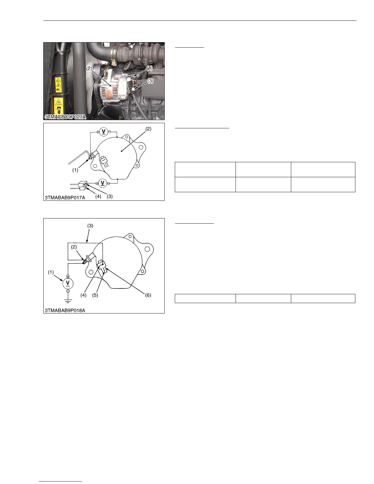
Alternator
1. Disconnect the 2P connector (3) from alternator after turning the
main switch OFF.
2. Perform the following checks.
W1026689
Connector Voltage
1. Turn the main switch OFF. Measure the voltage between the B
terminal (1) and the chassis.
2. Turn the main switch ON. Measure the voltage between the IG
terminal (3) and the chassis.
W1103012
No-Load Test
1. Connect the 2P connector (6) to previous positions of the
alternator after turning the main switch OFF.
2. Connect the jumper lead (3) between IG terminal (4) and B
terminal (2).
3. Start the engine and then set at idling speed.
4. Disconnect the negative cable from the battery.
5. Measure the voltage between the B terminal (2) and the chassis.
6. If the measurement is less than the factory specifications,
disassemble the alternator and check the IC regulator.
(Reference)
• Once the engine has started, the alternator temperature rises
quickly up to an ambient temperature of 70 to 90 °C (158 to 194
°F). As the temperature goes higher than 50 °C (122 °F), the
alternator voltage slowly drops; at higher than 100 °C (212 °F), it
drops by about 1 V.
W1102619
(1) B Terminal
(2) Alternator
(3) 2P Connector
Voltage
(Main switch at OFF)
B terminal - Chassis Approx. battery voltage
Voltage
(Main switch at ON)
IG terminal - Chassis Approx. battery voltage
(1) B Terminal
(2) Alternator
(3) IG Terminal
(4) L Terminal
Voltage Factory spec. More than 14 V
(1) Voltmeter
(2) B Terminal
(3) Jumper Lead
(4) IG Terminal
(5) L Terminal
(6) 2P Connector