8-S22
MX5100, WSM
HYDRAULIC SYSTEM
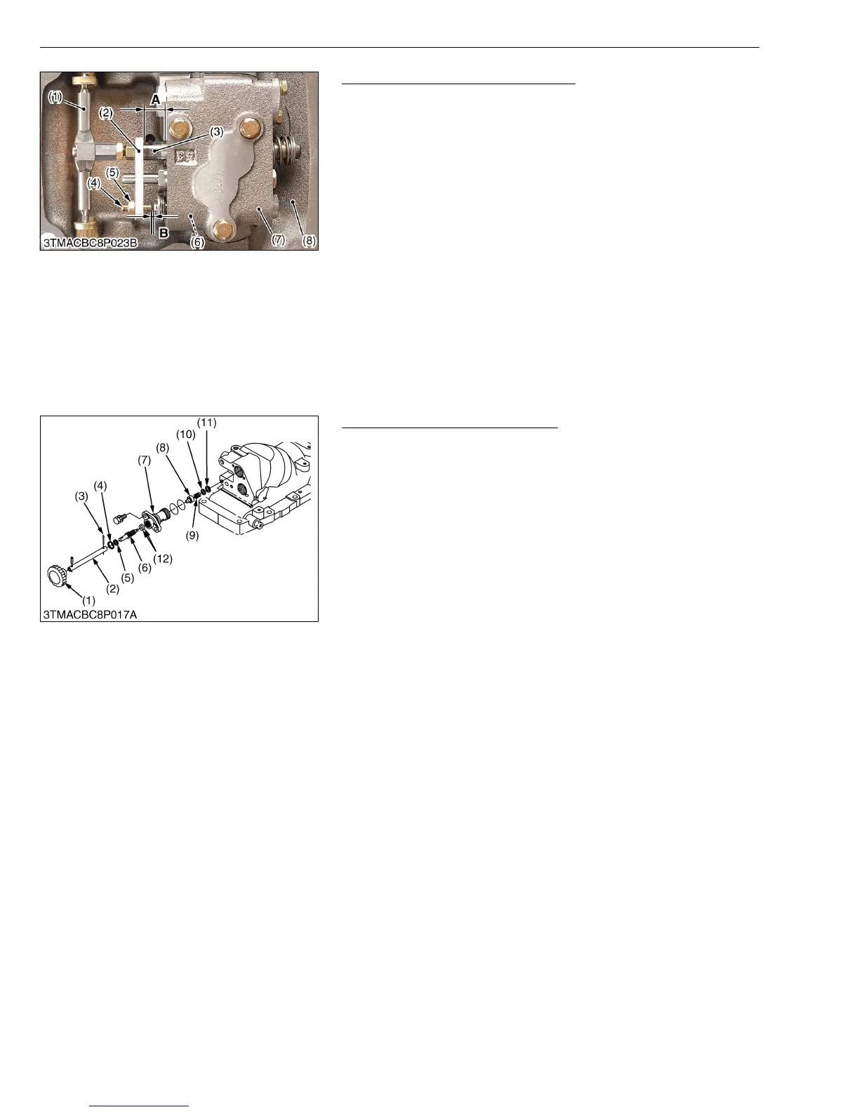
Assembling Position Control Valve
1. Install the position control valve (7) to the hydraulic cylinder (8).
2. Install the position control linkage including the position control
lever, the control arm, the spool drive lever (1), the feedback
lever shaft and the feedback rod.
3. Set the plate (1) parallel to the position control valve (7) by
moving the position control lever.
4. Set the dimension (A) between the plate 1 (2) and the control
valve to 16.0 to 16.3 mm (0.63 to 0.64 in.).
5. Turn and adjust the set screw (4) so that the clearance (B)
between the set screw (4) and the poppet 2 (6) is 0.1 to 0.2 mm
(0.0039 to 0.079 in.).
W1032363
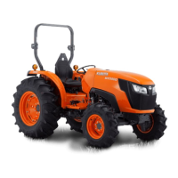
Lowering Speed Adjusting valve
1. Remove the lowering speed adjusting valve assembly from
hydraulic cylinder block.
2. Remove the internal snap ring (4), and remove the hydraulic
adjusting shaft (6).
3. Remove the internal snap ring (11), and draw out the spring (9)
and adjusting collar (8).
(When reassembling)
• Install the hydraulic adjusting shaft (6) to valve body (7), noting
two O-rings (12).
W1026106
(1) Spool Drive Lever
(2) Plate 1
(3) Spool
(4) Set Screw
(5) Nut
(6) Poppet 2
(7) Position Control Valve
(8) Hydraulic Cylinder
A : Dimension between the plate 1
and the control valve
B : Clearance between the set screw
and the poppet 2
(1) Grip
(2) Extension Shaft
(3) Split Pin
(4) Internal Snap Ring
(5) Washer
(6) Hydraulic Adjusting Shaft
(7) Valve Body
(8) Adjusting Collar
(9) Spring
(10) Washer
(11) Internal Snap Ring
(12) O-ring