2NM/2NX/2NY/2NZ/2P0/2P6
1-5-76
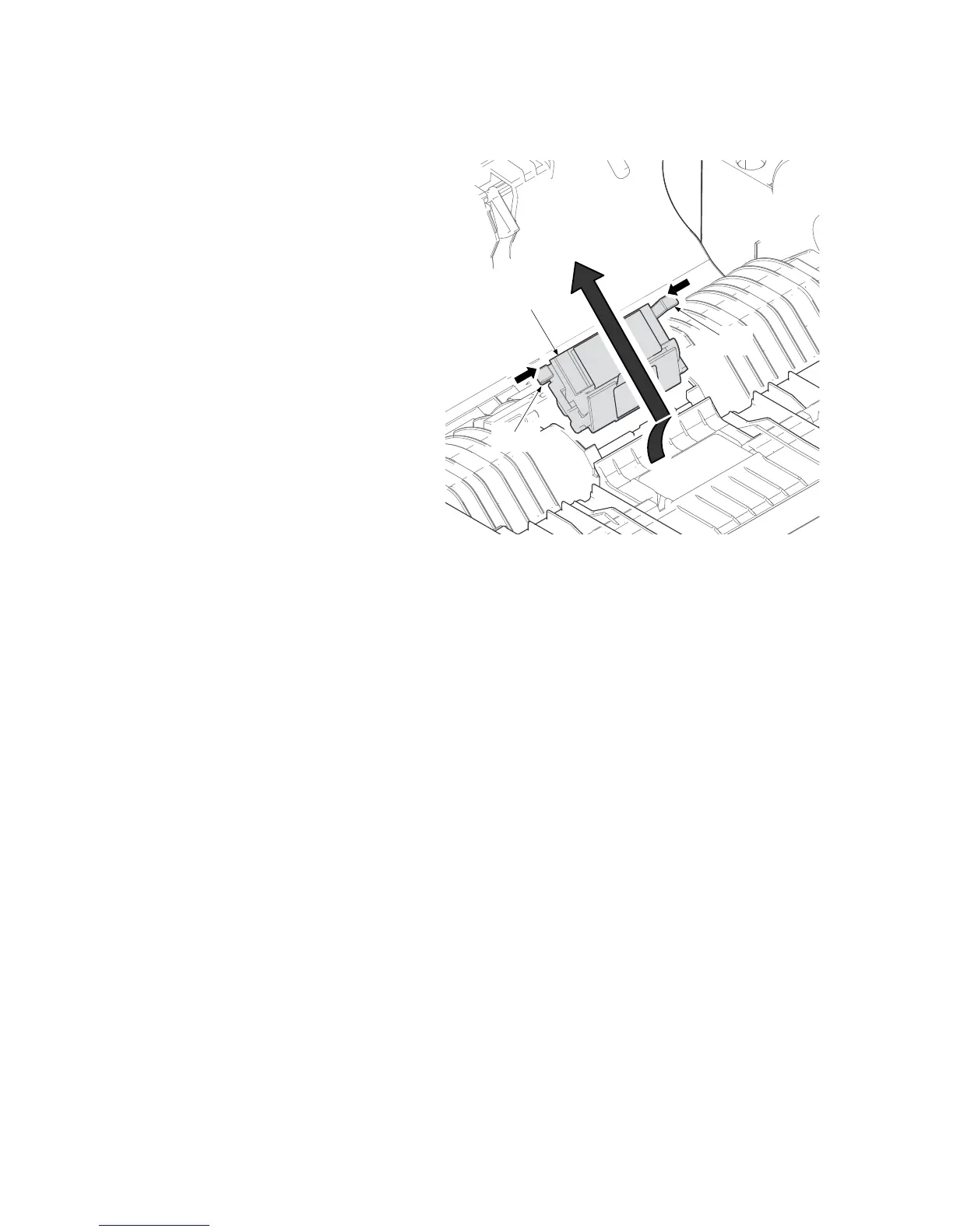
(1-2) Detaching and refitting the DP separation pad
Procedure
1. Push two hooks inside and pull DP sep-
aration pad assembly up.
2. Check or replace DP separation pad
and refit all the removed parts.
*: Check whether the pressure spring is
contained in the projection.
Figure 1-5-128
DP separation
pad assembly
Hook
Hook
 Loading...