2NM/2NX/2NY/2NZ/2P0/2P6
2-2-56
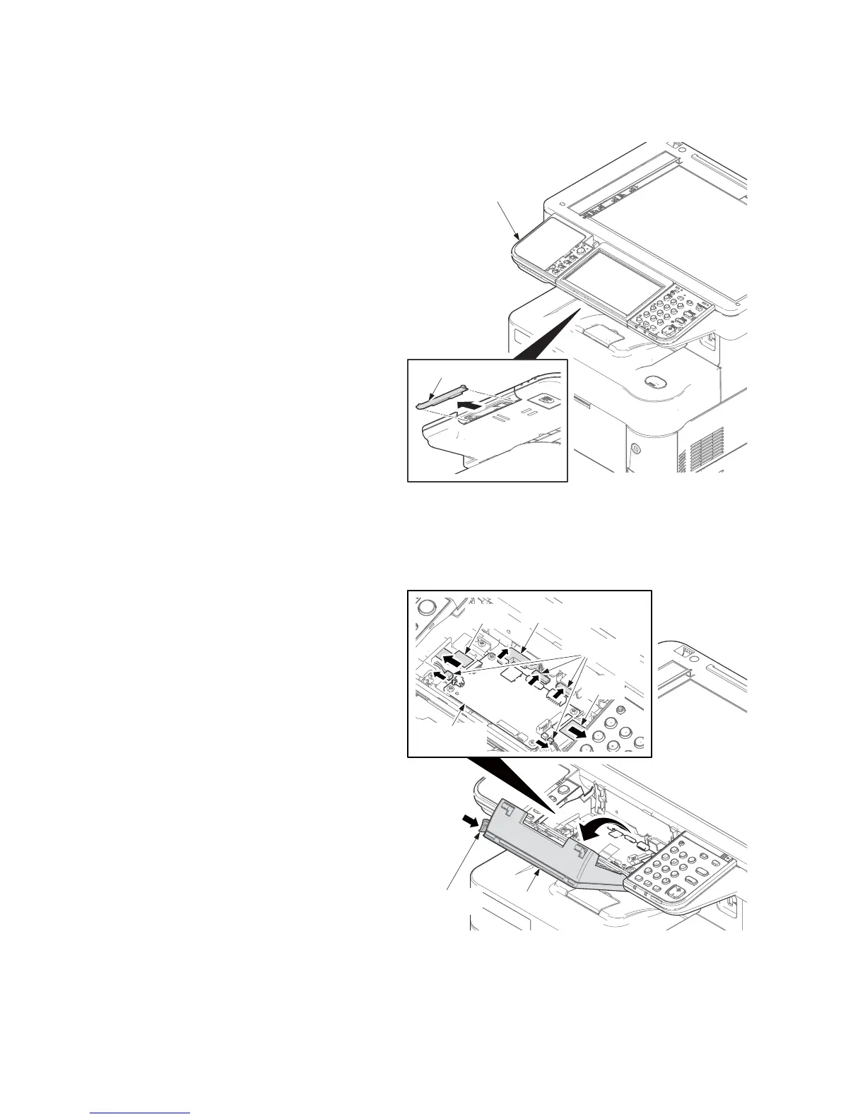
(4) Detaching and refitting the PWB. (OPPWB)
Procedure
1. Remove the LCD lower cover from the
operation panel assembly.
Figure 2-2-68
2. Raise the LCD forward during pushing
the lock lever.
3. Remove a USB connector, two FFCs
and four connectors from the operation
panel PWB.
Figure 2-2-69
LCD lower cover
Operation panel
assembly
LCD
Lock lever
Operation
panel PWB
FFC
USB connector
FFC
Connectors
 Loading...