124 User Manual QuickTOC
®
purity
ATEX 2 04E3920
7 How to Work With the Analyser
7.3 Good to know LAR | PROCESS ANALYSERS AG
The device has a so-called CAN circuit diagram. In the CAN circuit diagram, all parts of the device are
entered with their own ID. The device independently tests this plan and displays the results in this
screen. If, for example, a node is missing, this screen displays its name, ID and the suffix "not found".
This information is important to LAR technical support for troubleshooting.
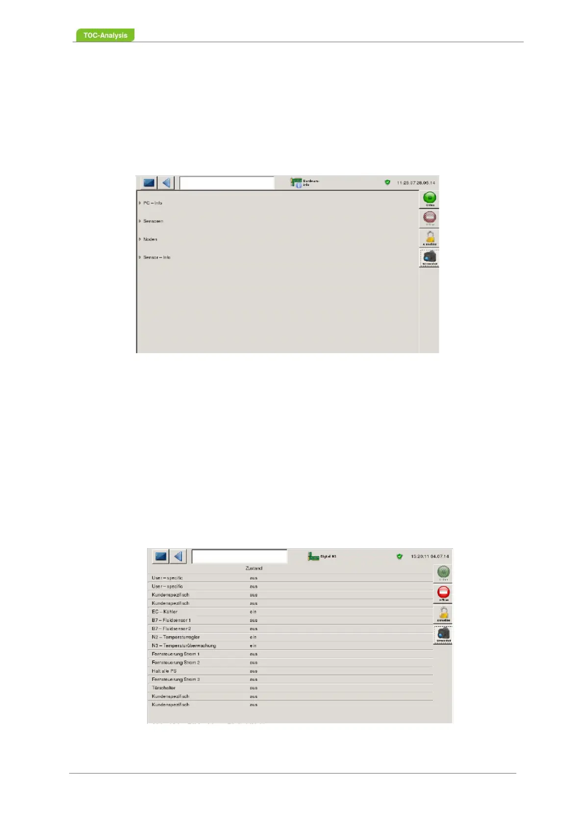
7.3.10.4 Hardware Info
Fig. 89: Hardware Info screen
This screen provides information about the hardware of the device:
• PC Info
• sensors
• Noden Info
• Sensor Info
Furthermore, the voltages of the analog inputs of the respective device parts are displayed.
7.3.10.5 DIGITAL IN 1, 2 and 3
These three screens show the status of digital inputs 1, 2 and 3. The values can be changed manually.
Fig. 90: DIGITAL IN 1 screen