04E3920 User Manual QuickTOC
®
purity
ATEX 2 43
3 Product
3.6 Components of the Explosion Protection
LAR | PROCESS ANALYSERS AG
3.6.4.2 RS232 Serial Interface
The serial RS232 interface can be used to transfer the current data to a remote computer unit that is
connected to the analyser via an RS232 cable. The pin assignment of the interface is shown in Fig. 27,
page 42. Set the serial interface parameters on your computer as follows:
Formats:
• Date; time: dd.mm.yyyy-hh:mm:ss
• Display measured values: @@@@@@.@@ (six digits before and two digits after the comma,
not used digits are displayed as „Zero“)
• Status (Example): "Errors = (E1835_E1836)" ; "Limits = (L1_max LV1_max)" ; "Status = (M1)"
(Underscore = blank space)
Various activities are listed in the status string. The maximum length of the transmitted string is 4095
characters.
3.6.4.3 Digital Inputs
The analyser can be controlled via the digital inputs. This option allows e.g. to start only one measure-
ment if a sample is present. The necessary input signals (0 - 24 VDC) must be provided by the user:
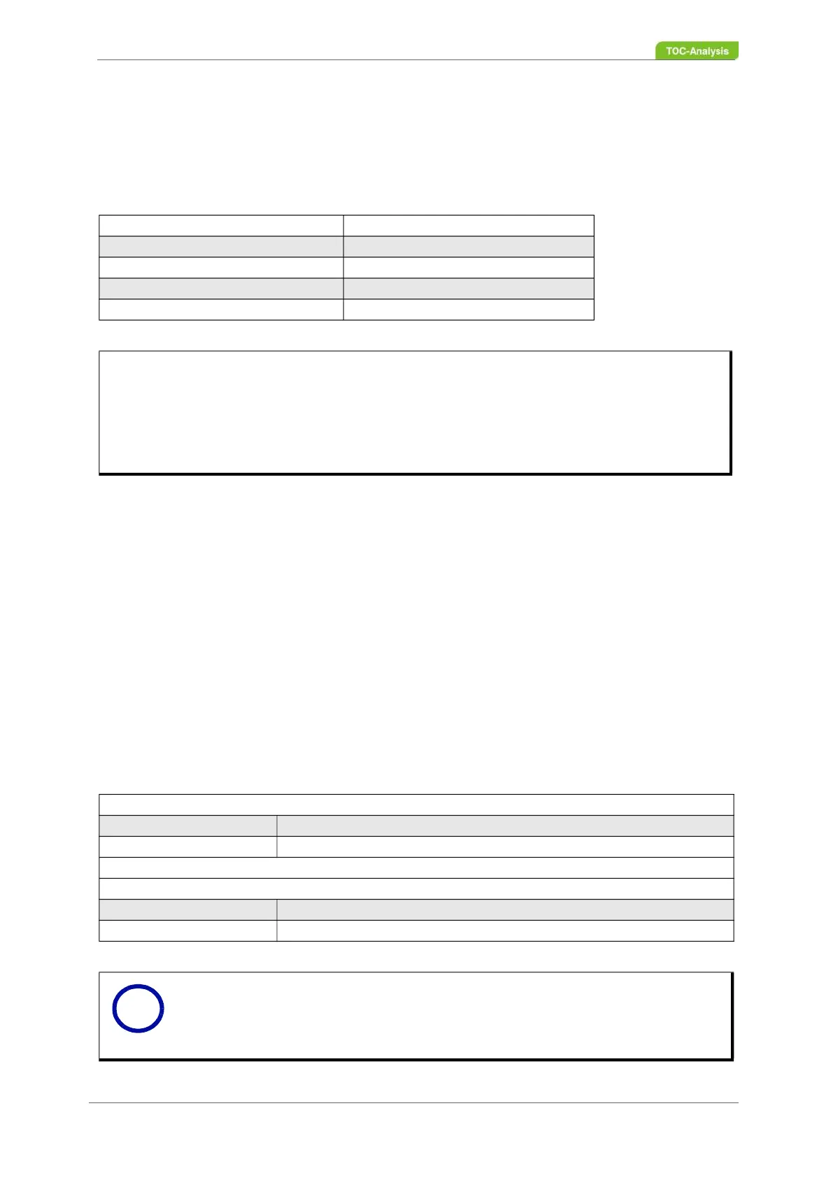
Tabelle 3: Serial interface parameters
Baud rate 9600Bd
Parity none
Data bits 8
Stop bits 1
Protocol Xon / Xoff
Example:
If you send the letter D, the analyser will reply with the transmission of the current data in the following
format:
Date; time; measured value display1; measured value display2; ... last measured value display; re-
spective status
Tabelle 4: Digital input of the applied DC voltage
Digital Input 1, 2, 4, 5, 6, 7 (Sample Measurement)
0 - 3 V no changes
12 - 24 V Measurement
Digital input 3 (General Stop of the Analyser)
0 - 3 V no changes
12 - 24 V measurement is stopped
Notice
The digital inputs are assigned to the corresponding sample streams. For an overview
see Fig. 27.
i