04E3920 User Manual QuickTOC
®
purity
ATEX 2 103
7 How to Work With the Analyser
7.2 Configuration
LAR | PROCESS ANALYSERS AG
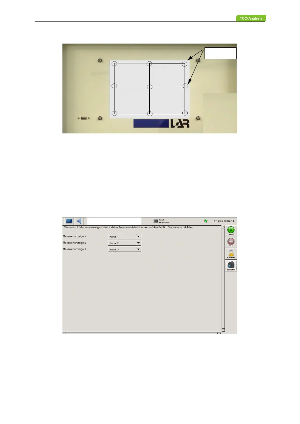
5. After pressing all nine calibration points, the view returns to the PC Settings screen.
Fig. 65: Calibrate touchscreen
7.2.8 Channel Display
In the "Channel display" view, the measured value displays can be defined. A channel is defined by sam-
ple flow, sensor, function, parameters and channel parameters. These settings are factory-set and can
be viewed in user level 3 under the "Names and Units" screen (Chapter 7.3.14 from page 131). The first
8 measured values (channel display) can be viewed in the measured value screen. The settings of the
channel display are set with the requirements of the device. If the channel display has to be changed,
the processing can be done by means of the corresponding selection boxes..
Fig. 66: Channel display (Example)
Coordinates