04E3920 User Manual QuickTOC
®
purity
ATEX 2 41
3 Product
3.6 Components of the Explosion Protection
LAR | PROCESS ANALYSERS AG
3.6.4 Electronic Connections (Digital and Analog Connections)
3.6.4.1 Connections on the TRC-Board
The analyser is equipped with a TRC board for connection to external devices or to a process control
system. It is located on the upper left side of the mounting plate in the rear housing (Fig. 25, page 40).
Open the rear housing door to gain access to the TRC board.
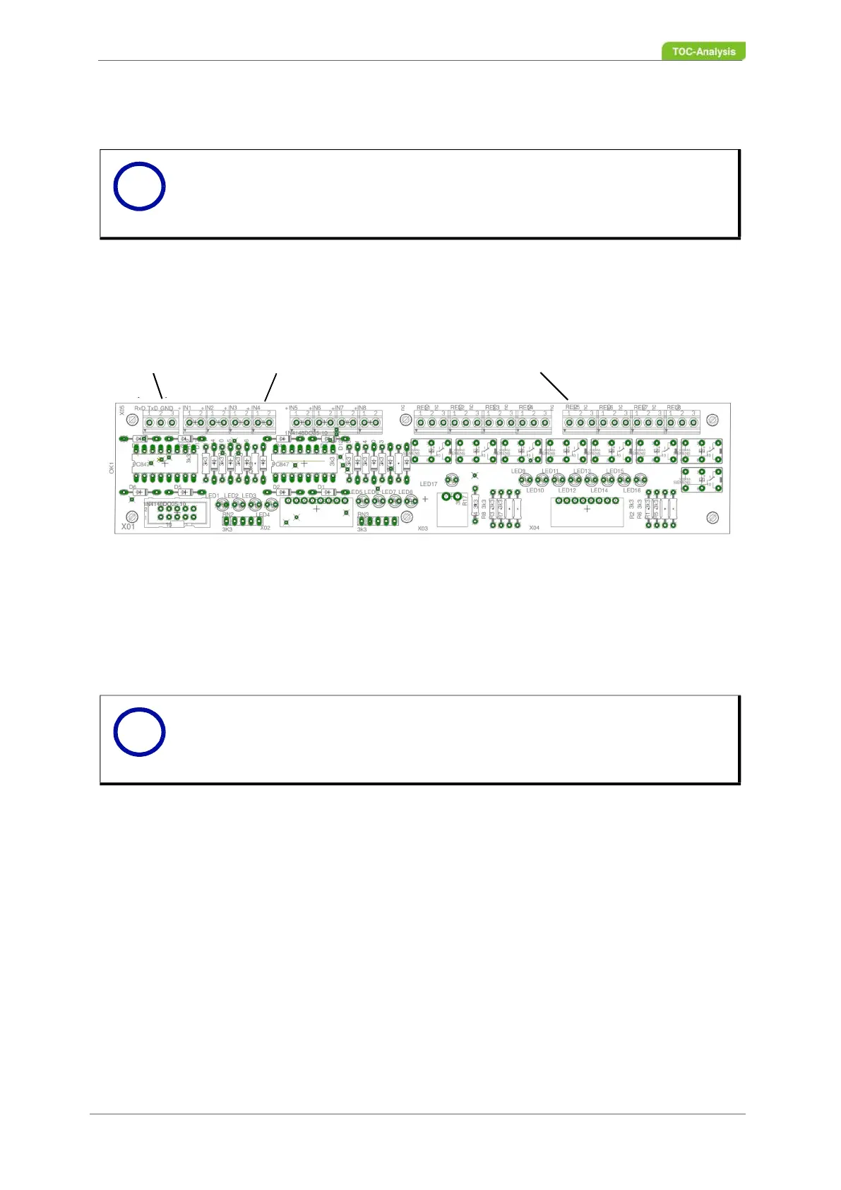
Fig. 26: TRC-Board (complete)
The TRC board has the following connections
• 1x RS 232 interface
• 8x Digital inputs
• 8x Relays
Notice
De-energize the analyser before beginning to cabling the system.
Notice
For connecting the signal cables to the TRC board, use a cable cross-section of
1.5 mm
2
= cable diameter of 1.4 mm.
i
i