LDI Intellectual Property.
Not for secondary distribution or replication, in part or entirety.
DIGISONDE-4D
SYSTEM MANUAL
VERSION 1.2.11
SECTION 4 – HARDWARE DESCRIPTION 4-9
orthogonal antennas. The transmitter design features two digital up-converters AD9857 by Analog Devices
that can be independently programmed to have + or -90 of inter-channel phase difference (or 0º if linear
polarization is required).
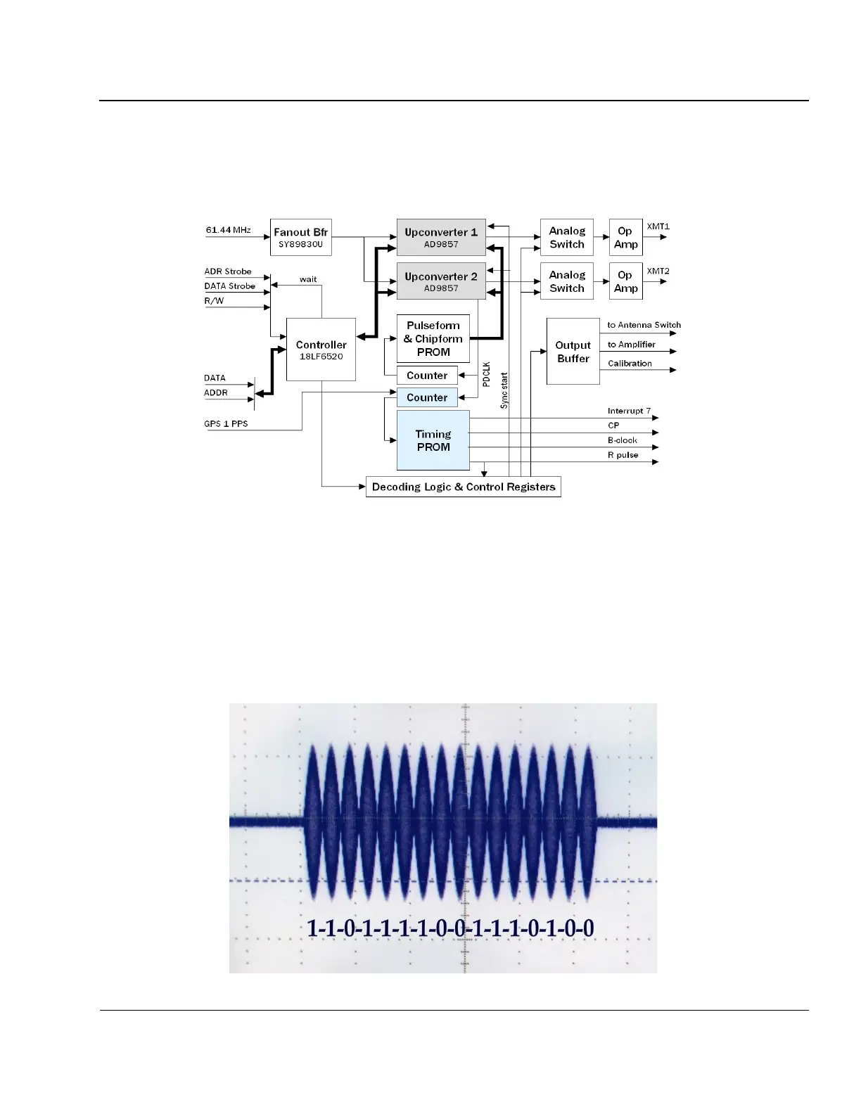
Figure 4-5: Digital Transmitter Block Diagram
4:7. Both upconverters produce RF phase-coded pulses at the selected operating frequency using 16-chip
Golay complementary codes. Onboard flash memory stores 16-chip code 1 and 2 sequences, as well as a 66
µs uncoded waveform, 64-chip, and 128-chip complimentary codes. The 64-chip and 128-chip complimen-
tary coded waveforms are designed for oblique operation only. A sinusoidal chip shape is provided for
DPS4D transmission (see Figure 4-6). Changing the chip waveform shape from square-wave to sinusoidal
results in a narrower transmission bandwidth. Initial measurements show that at 40dB below the main signal
the sinusoidal waveform chip is 4 times narrower than its square-wave equivalent. Cleaner transmission
comes at the expense of reduced transmitter power associated with the sinusoidal chip form, which was
compensated by additional processing of the received signal.