LDI Intellectual Property.
Not for secondary distribution or replication, in part or entirety.
DIGISONDE-4D
SYSTEM MANUAL
VERSION 1.2.11
SECTION 1 - GENERAL SYSTEM DESCRIPTION 1-17
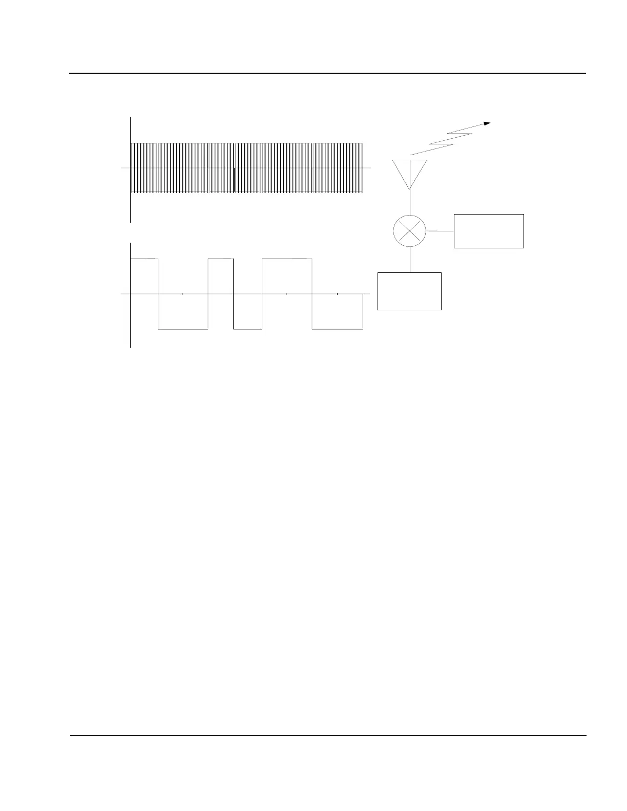
Figure 1-9: Generation of a Bi-phase Modulated Spread Spectrum Waveform
NOTE
Notation throughout this chapter will use s(t) as the transmitted signal, r(t)
the received signal and p(t) as the chip sequence. Functions r
1
(t) and r
2
(t) will
be developed to describe the signal after various stages of processing in the
receiver.
The term chip is used rather than bit because for spread spectrum communications many chips are required to
transmit one bit of message information, so a distinct term had to be developed. Figure 1-10 on the following
page depicts the modulation of a sinusoidal RF carrier signal by a binary code (notice that the code is a zero
mean signal, i.e., centered around 0 volts amplitude). Since the mixer in Figure 1-9 can be thought of as a
mathematical multiplier, the code creates a 180
o
( radians) phase shift in the sinusoidal carrier whenever p(t) is
negative, since –sin(t) = sin(t+).
1:33. The binary spreading code is identical to a stream of data bits except that it is designed such that it
forms a pattern with uniquely desirable autocorrelation function characteristics as described later in this chap-
ter. The 16-bit Complementary Code pair used in the Digisonde-4D is 1,1,-1,1,1,1,1,-1,-1,1,1,1,-1,1,-1,-1 mod-
ulated onto the odd-numbered pulses and -1,-1,1,-1,-1,-1,-1,1,-1,1,1,1,-1,1,-1,-1 modulated onto the even-
numbered pulses. This pattern of phase modulation chips is such that the frequency spectrum of such a signal
(as shown in Figure 1-10) is uniformly spread over the signal bandwidth, thus the term “spread spectrum”. In
fact, it is interesting to note that the frequency spectrum content of the spread spectrum signal used by the DPS
and Digisonde-4D is identical to that of the higher peak power, simple short pulse used by the Digisonde-256,
even though the physical pulse is 8 times longer. Since they have the same bandwidth, Equation 1-4 would
suggest that they have the same range resolution. It will be shown later in this chapter, that the ability of the
Digisonde- 256 and the DPS to determine range (i.e., time delay), phase, Doppler shift and angle of arrival is
also identical between the two systems, even though the transmitted waveforms appear to be vastly different.