LDI Intellectual Property.
Not for secondary distribution or replication, in part or entirety.
DIGISONDE-4D
SYSTEM MANUAL
VERSION 1.2.11
SECTION 4 – HARDWARE DESCRIPTION 4-23
4:43. For signals arriving from remote stations with larger than 45° zenith angles the suppression of un-
wanted polarization depends strongly on the orientation of the turnstile antennas. An optimum configuration
would be for the loop planes to be 45° off the direction toward the remote sounder.
POWER DISTRIBUTION CARD
4:44. Power distribution within the sounder chassis is centralized in the Power Distribution (PWR) Card
(shown in Figures 4-20 and 4-21). Fusing (with self-resetting overload devices), voltage regulation and cur-
rent limiting are applied as necessary. Along the top of the card are LED’s to indicate the presence of various
voltages. Red LED’s indicate a positive voltage, green indicate negative voltages and amber indicate the 24
V – 28 V input power for all DC/DC converters. An auxiliary function of this card is to switch the voltage
level of the power sent to the magnetic loop preamplifiers to switch received polarization sensitivity (left-
hand and right-hand circular). The card also provides a mounting for the DC/DC converters and collects
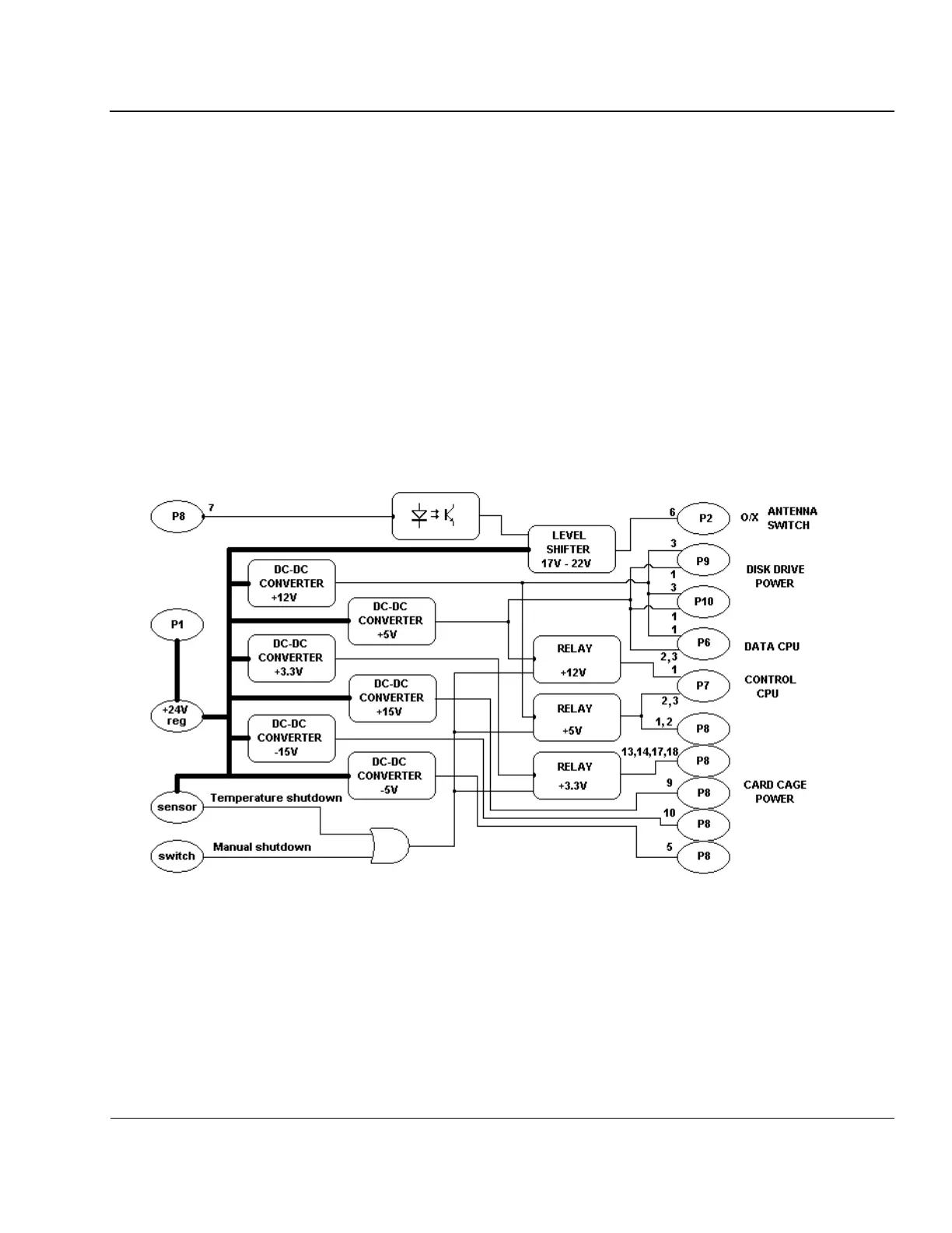
several BIT signals into connector P5 to output them to the BIT Card. Figure 4-22 shows the overall power
distribution within the sounder system.
Figure 4-19: Power Distribution Card Block Diagram (System Power)