LDI Intellectual Property.
Not for secondary distribution or replication, in part or entirety.
DIGISONDE-4D
SYSTEM MANUAL
VERSION 1.2.11
5-36 SECTION 5 - SYSTEM SOFTWARE – ANNEX A
Built-In Test Operation
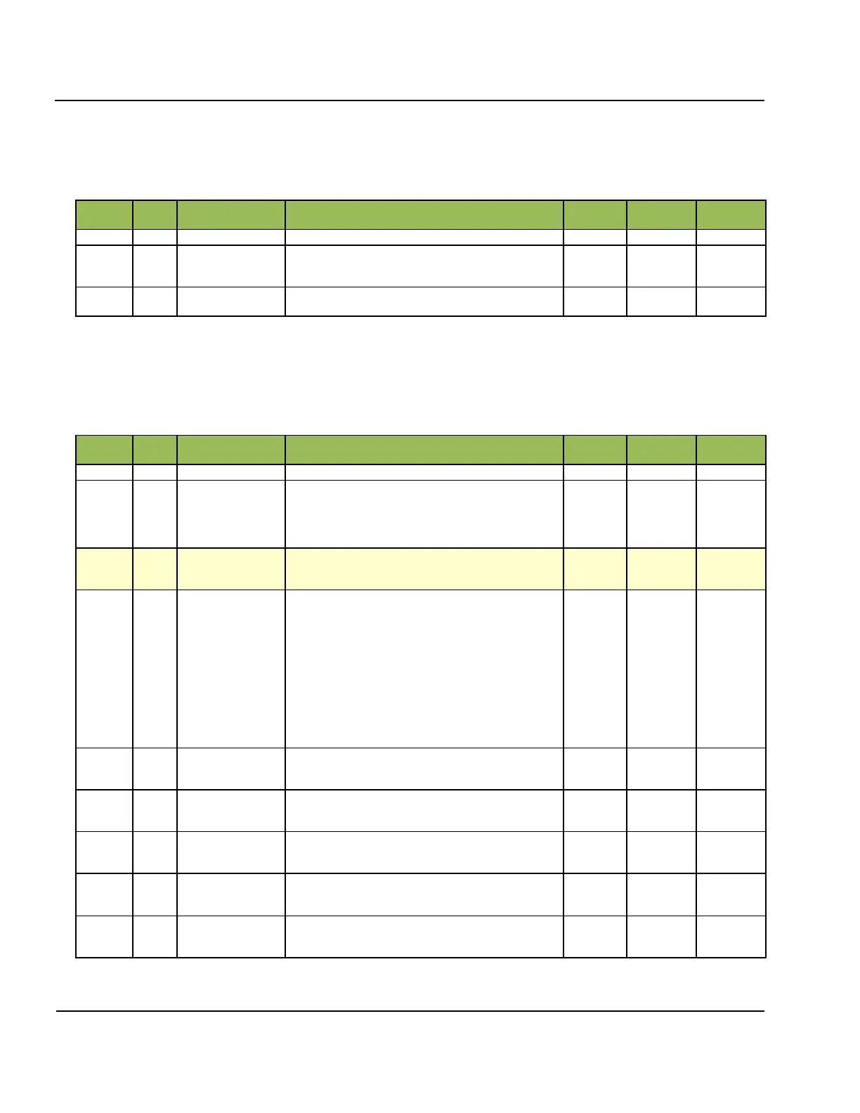
Table 5A- 8 contains description of the Built-in Test Program.
Table 5A- 8: Built-in Test Operation Version 3 (Length 4 Bytes)
Operating code. Contains constant 2.
Operation option:
0 = Measurement
1 = SW (software) test pattern
Frequency
Run BIT on this frequency
Cross-Channel EQ Operation
Table 5A- 9 contains description of the Channel EQ Program.
Table 5A- 9: Channel Equalizing Operation Version 3 (29 Bytes)
Operating code. Contains constant 3 (Channel EQ).
Operation option:
0 = Measurement
1 = Internal loopback
2 = HW (digitizer card hardware) test pattern
3 = SW (software) test pattern
All data processing steps applied to acquired sample
data.
Data Pro-
cessing
structure
Processing done prior to delivery of data to DCART.
Notes:
Although DCART can run all processing steps described
by ALL_PROC, these steps can be delegated, partially or
completely, to the Digisonde
®
hardware and the embedded
computer system, thus relieving DCART from some of the
work to be done. It is possible to control where particular
processing steps occur by specifying DESC_PROC.
Data Processing that have been applied by DESC will be
reflected in corresponding field of Data Preface structure
and it will not exceed Data Processing described by this
field.
Data Pro-
cessing
structure
Lower Frequency Limit
This field’s used when Frequency Stepping Law is Linear
or Logarithmic
Upper Frequency Limit
This field’s used when Frequency Stepping Law is Linear
or Logarithmic
Coarse Frequency Step
This field’s used when Frequency Stepping Law is Linear
or Logarithmic
Waveform
1 = 16-chip complimentary code
2 = 67 s short pulse
Interpulse phase switching (constant, set to disabled)
0 = disabled
1 = enabled