LDI Intellectual Property.
Not for secondary distribution or replication, in part or entirety.
DIGISONDE-4D
SYSTEM MANUAL
VERSION 1.2.11
1-44 SECTION 1 - GENERAL SYSTEM DESCRIPTION
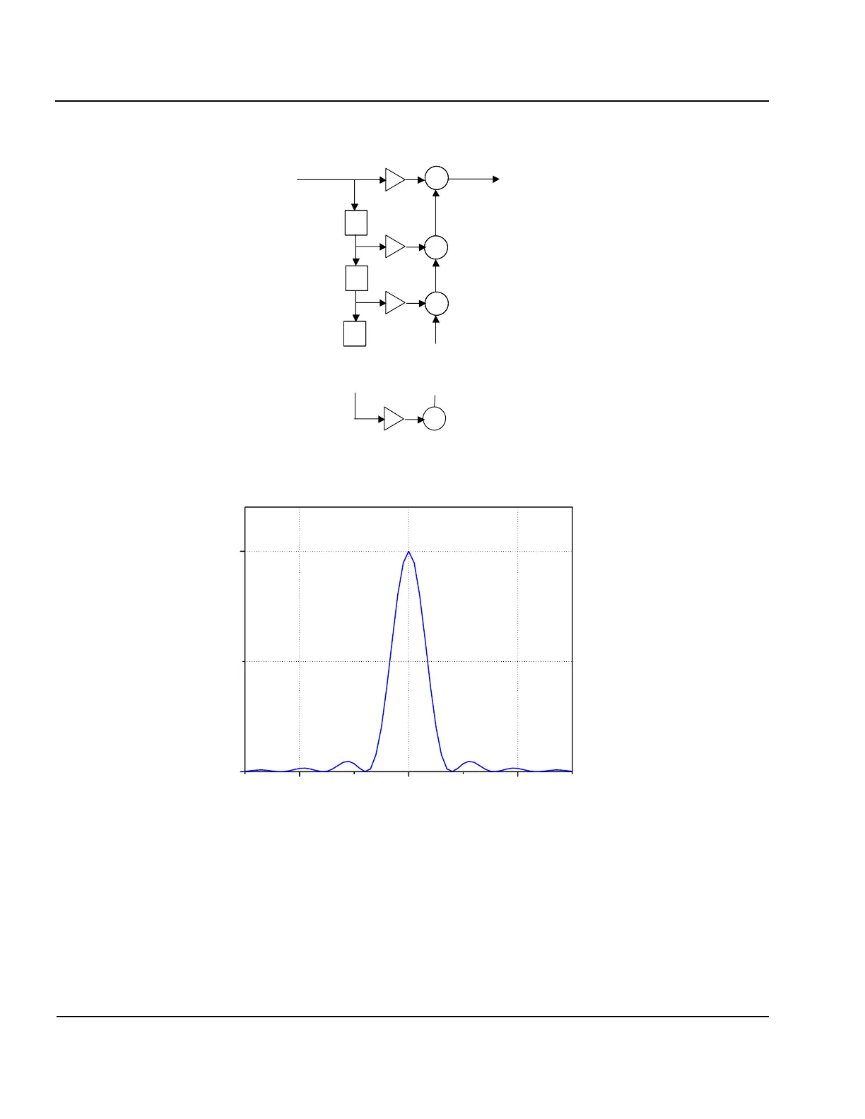
Figure 1-26: System Diagram of a FIR Filter (Samples Delayed by a Number of Unit Delays
(Denoted by z
-1
) are Summed with Corresponding Tap Coefficients
k
.)
Figure 1-27: Calculated Amplitude Frequency Characteristic of the Digital Filter
RF SYSTEM DESIGN CONSIDERATIONS
1:98. The detailed design and synthesis of a RF measurement system (or any electronic system) must be
based on several criteria:
a. The performance requirements necessary to provide the needed functions, in this case scientific
measurements of electron densities and motions in the ionosphere.
b. The availability of technology to implement such a capability.
++
++
++
z
-1
z
-1
z
-1
+
z
-1
z
-1
z
-1
z
-1
z
-1
z
-1
. . . . . . . .
1
x(n)
y(n)