LDI Intellectual Property.
Not for secondary distribution or replication, in part or entirety.
DIGISONDE-4D
SYSTEM MANUAL
VERSION 1.2.11
SECTION 4 – HARDWARE DESCRIPTION 4-13
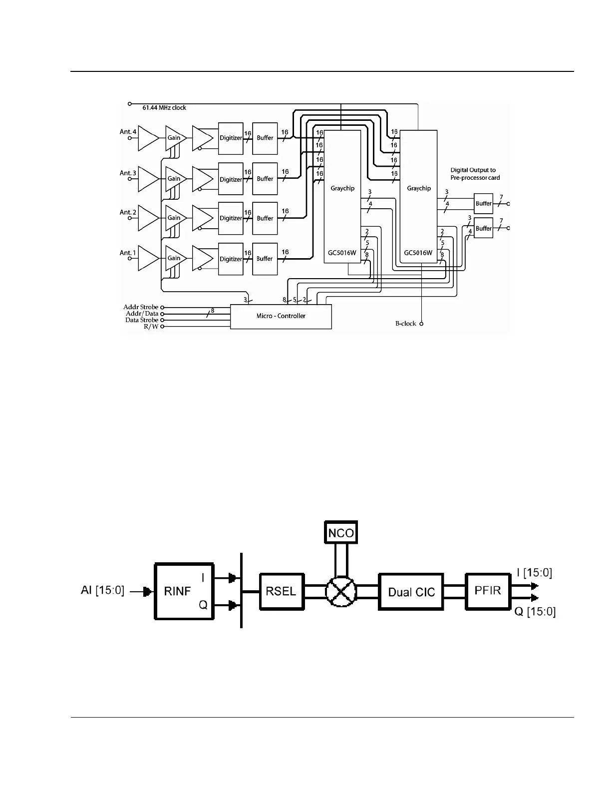
Figure 4-8: Digital Receiver Block Diagram
(Only One of the Graychips is Used for Current Operation)
4:21. A table of automatic gain selections for each of the operating frequencies is stored at the Control
Platform and continuously updated with each run of the gain evaluation programs that cover frequencies
from 0.1 to 30 MHz with 600 50 kHz steps. This table holds the gain settings for each frequency that will be
used in the next ionogram sounding.
Digital Receivers with TI Graychip
4:22. The Digital Receiver is designed around the Texas Instrument Graychip GC5016 (Figure 4-8) which
has four independent digital synthesizers and four 16-bit digital inputs. Figure 4-9 shows the functional
block diagram for one channel of the GC5016 chip configured as a digital down-converter.
Figure 4-9: Block Diagram of a Single Channel of the GC5016 Chip
(RINF is receive input formatter, RSEL is receive input channel selector, NCO denotes digital oscilla-
tor, CIC is cascade integrator comb filter, and PFIR is programmable finite impulse response filter.)