LDI Intellectual Property.
Not for secondary distribution or replication, in part or entirety.
DIGISONDE-4D
SYSTEM MANUAL
VERSION 1.2.11
5-24 SECTION 5 - SYSTEM SOFTWARE
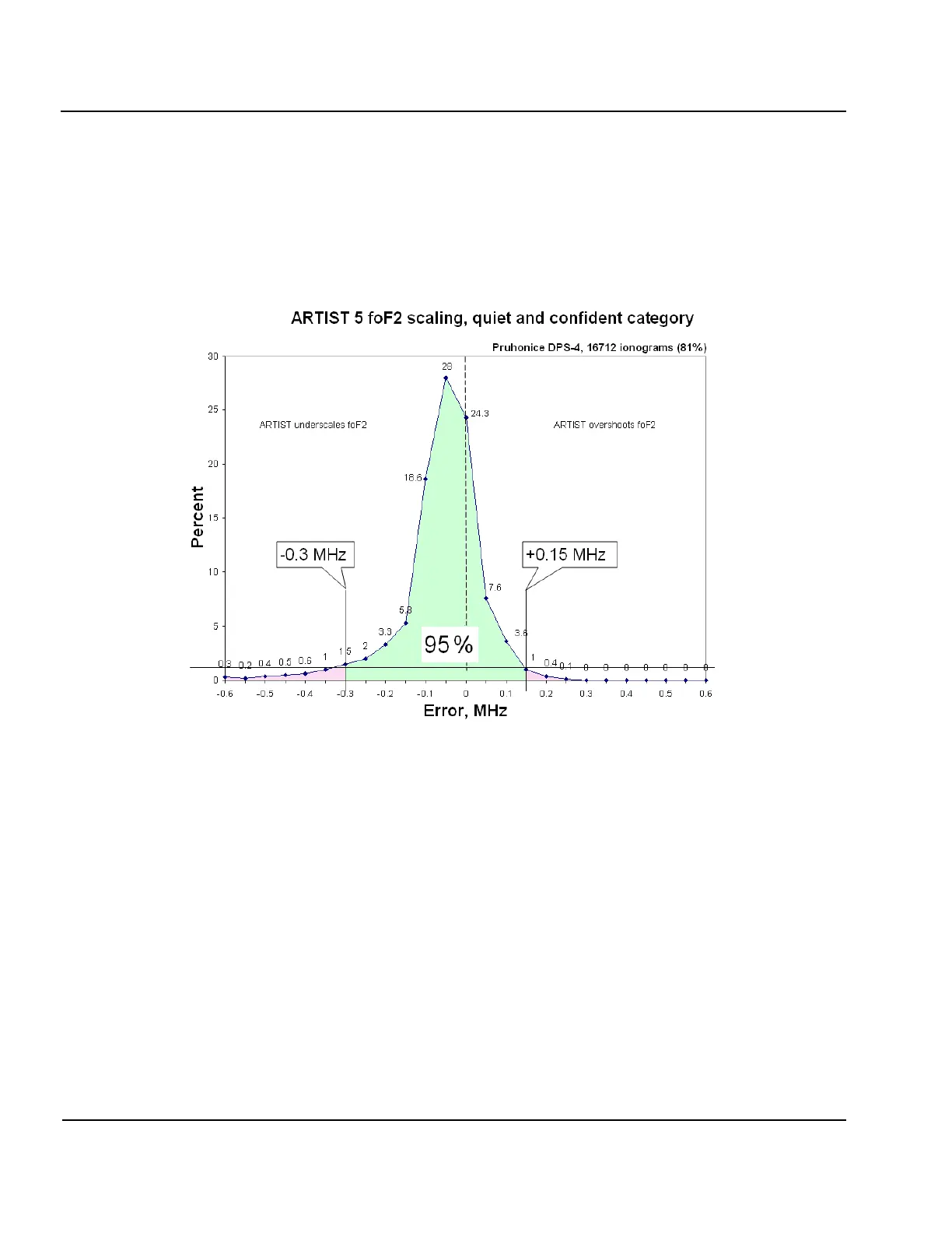
5:49. Figure 5-7 illustrates the benefits of sorting ionograms in subcategories to statistically capture differ-
ences of autoscaling performance for different classes of ionograms. It shows the error histogram built using
only ionograms taken during quiet ionospheric conditions and autoscaled with at a high confidence level (iono-
gram qualifier QC). Comparison of Figure 5-6 and Figure 5-7 shows improvement of the lower error bound
enclosing 95% of all data from 0.45 to 0.3 MHz.
Remarkably, 81% of all ionograms taken at Průhonice, a typical mid-latitude location, fall in the QC category
(quiet ionosphere, confidence scaling). Similar ratio has been observed at other mid-latitude locations.
Figure 5-7: Error histogram of autoscaled critical frequencies of F2 layer obtained for
16,712 ionograms from DPS4 ionosonde at Průhonice taken during quiet ionospheric
conditions and auto-qualified as high confidence.
Lower bound for foF2 error bar specification has improved from -0.45 to -0.3 MHz
in comparison to the all ionogram case shown in Figure 5-6.
Error Boundaries for EDP
5:50. Figure 5-8 illustrates the placement of the error boundaries on EDPs derived from the ionograms. Inner
and outer boundaries are calculated using two Chebyshev polynomials representing the profile shape that are
derived from the original profile coefficients to fit anchor points that are placed at the error bars for the critical
frequencies, the valley between E and F regions, and the unknown starting height of the ionosphere. To avoid
crossing of the boundaries in the valley region between E and F layers, the inner boundary gets a wider valley
width W
in
and a deeper valley depth D
in
, and the outer boundary has a narrower valley W
out
and shallower depth
D
out
(see insert in Figure 5-8).