LDI Intellectual Property.
Not for secondary distribution or replication, in part or entirety.
DIGISONDE-4D
SYSTEM MANUAL
VERSION 1.2.11
1-22 SECTION 1 - GENERAL SYSTEM DESCRIPTION
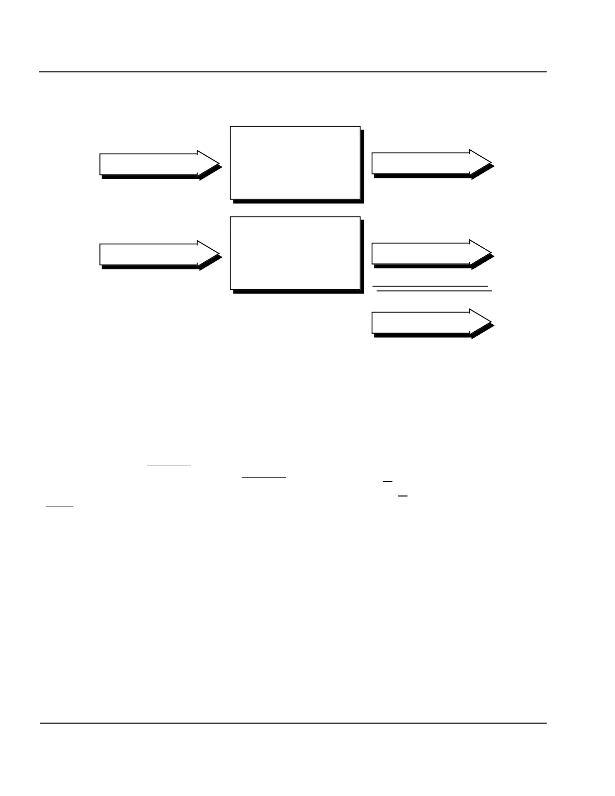
Figure 1-13: Illustration of Complementary Code Pulse Compression
1:41. The amplitude coefficient M in Equation 1-10 is tremendously significant! It is what makes spread-
spectrum techniques practical and useful. The M means that a signal received at a level of 1 μV would result in
a compressed pulse of amplitude M μV, a gain of 20·log
10
(M) dB. Unfortunately, the benefits of all of that gain
are not actually realized because the RMS amplitude of the random noise (which is incoherently summed by
Equation 1-10) which is received with the signal goes up by a factor of
√
𝑀. However, this still represents a
power gain (since power = amplitude
2
) equal to M, or 10·log
10
(M) dB. The
√
𝑀 coefficient for the incoherent
summation of multiple independent noise samples is developed more thoroughly in the following section on
Coherent Spectral Integration, but the factor of M-increase for the coherent summation of the signal is clearly
illustrated in Figure 1-13.
1:42. The next concern is that the pulse compression process is still valid when multiple signals are superim-
posed on each other as occurs when multipath echoes are received. It seems likely that multiple overlapping
signals would be resolved since Equation 1-9 and the free space propagation phenomenon are linear processes,
so the output of the process for multiple inputs should be the same as the sum of the outputs for each input sig-
nal treated independently. This linearity property is illustrated in Figure 1-14. Two 4-chip input signals (a 4-
bit code is used in this figure for ease of illustration), one three times the amplitude of the other, are overlapped
by two chips at the upper left of the illustration. After pulse compression, as seen in the lower right, the two
resolved components, still display a 3:1 amplitude ratio and are separated by two chip periods.
VIS1-7
Odd #'d Pulses
Even #'d Pulses
— —
–a a –a –a
— —
— —
a a a –a
— —
Code 1
Matched Filter
Code 2
Matched Filter
— — — — — —
—
–1 1–1 –1
—
— — — — — —
—
1 1 1 –1
—
—
a
—
–a 4a –a
—
a
—
+
—
–a
—
a 4a a
—
–a
—
— — — —
8a
— — — —
=
r
2
= s[k-n] h[k]
y
1
= a p 1[k-n] p
1
[k]
y
2
= a p
2
[k-n] p
2
[k] r
2
= y
1
+ y
2