LDI Intellectual Property.
Not for secondary distribution or replication, in part or entirety.
DIGISONDE-4D
SYSTEM MANUAL
VERSION 1.2.11
2-10 SECTION 2 - INSTALLATION, SETTING UP AND FIELD VALIDATION
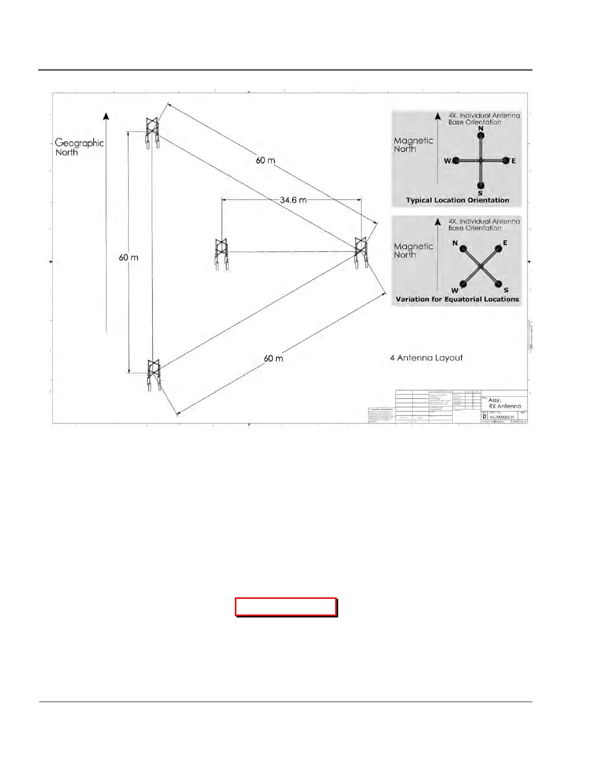
Figure 2-3: Standard Receive Antenna Array
Antenna Cable Connections
2:34. Connect each transmit, receive, and GPS antenna directly to the Surge Protectors then to the back of
the Sounder using the supplied 7.6 m RG-58 cable, with a MALE “N” type connectors. The four receive an-
tennas cable lengths must be matched to within 6 inches or 20 cm of each other. The maximum receive an-
tenna cable length for RG-213 is 300 m, and depending on the local RF noise environment, shorter lengths
many be suggested. For distances greater than 300 m use of a Heliax type cable is suggested.
2:35. Connect the two transmit antenna cables to the Surge Protectors then to the XMT1 and XMT2 outputs
on the sounder’s rear I/O panel using the supplied 7.6 m RG-58 cable.
CAUTION
EACH ANTENNA MUST ONLY BE CONNECTED TO ITS RESPECTIVE REAR I/O
PANEL CONNECTOR ( E.G., ANTENNA #1 TO CONNECTOR #1)