LDI Intellectual Property.
Not for secondary distribution or replication, in part or entirety.
DIGISONDE-4D
SYSTEM MANUAL
VERSION 1.2.11
SECTION 6 - MAINTENANCE 6-27
ANTENNA SUB-SYSTEMS
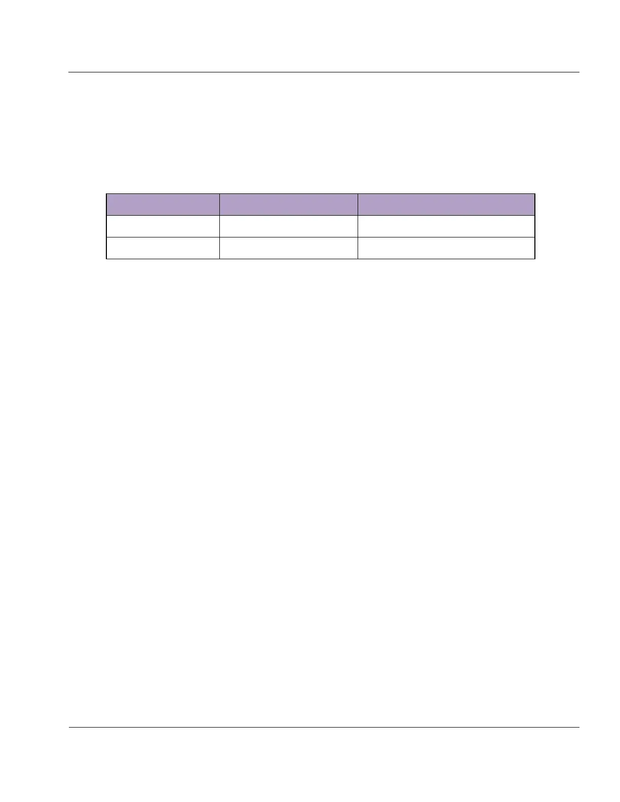
6:76. Table 6-6 lists BIT faults (refer to Built-In Test Display Figure, Figure 6-18) pertaining to the Receive
and Transmit Antenna sub-systems.
Equipment needed: None
Table 6-6: BIT Faults of the Receive and Transmit Antenna Sub-system
Fault occurs when an RX antenna is
faulty.
Fault occurs when VSWR mismatch is
detected on either TX antenna
6:77. Periodic evaluation of RX Antenna sub-systems is performed by the BIT program. If a bad channel is
indicated, cables from the receive antennas can be swapped on the rear panel of the DPS or at the Lightning
Protection Bracket to check for a bad cable or antenna preamp; however, they must be returned to their original
positions once the antenna has been repaired to ensure the Drift (.dft) data displays correct directional infor-
mation. O/X switching voltage (17-22 VDC) can be measured at the antenna preamp on the N-type connector.
No voltage can indicate a break in the receive cable. If a TDR (Time Domain Reflectometer) is available it may
be used to locate the cable break.
CHAPTER 3
TROUBLESHOOTING
REPAIR OF FAILED MODULES
6:78. LRM troubleshooting will normally be performed under special arrangements with the manufacturer.
The LRM to be diagnosed may have been found faulty by the Built-In Test at the operating site, or by finding
that replacement of the LRM returned the system to normal operating status. To assist with the identification of
discrete components and non-specialized fault finding on proprietary circuit boards, a technical data package
comprised of circuit board layouts, parts lists, and schematics is provided separately to the customer.
6:79. Due to the small size and density of the integrated circuits on the LRM’s in the main chassis, it is rec-
ommended that the boards be diagnosed and repaired by the manufacturer. Without proper tools and experience
it is easy to damage these boards.
6:80. It is possible for a customer to test and repair some of the modules outside the main chassis. Diagnostic
procedures are included in the following paragraphs.
6:81.
TROUBLESHOOTING DATA COMPUTER