LDI Intellectual Property.
Not for secondary distribution or replication, in part or entirety.
DIGISONDE-4D
SYSTEM MANUAL
VERSION 1.2.11
4-22 SECTION 4 – HARDWARE DESCRIPTION
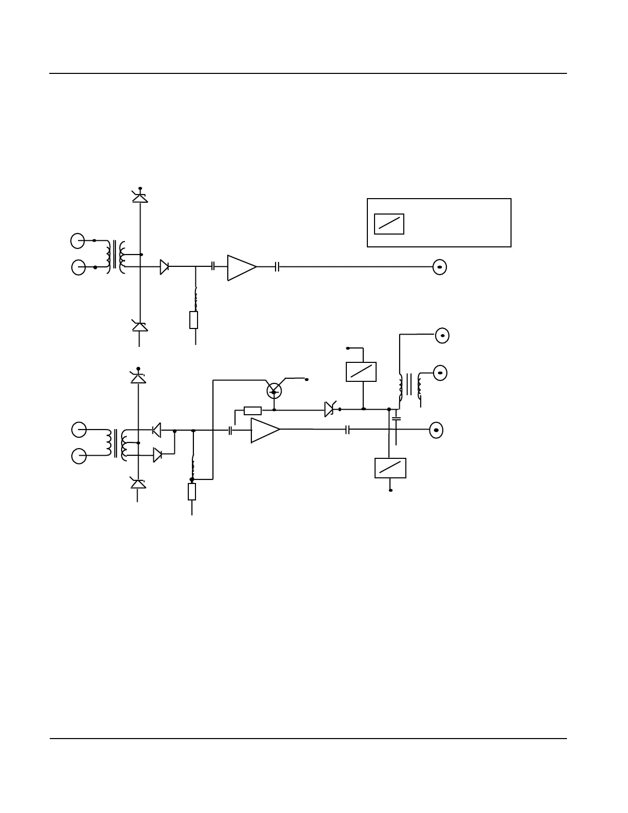
POLARIZATION SWITCH
4:39. With two channels, one for the North (N) – South (S) loop and another for the West (W) – East (E)
loop, the Polarization Switch (Figure 4-18) allows the receiver to receive circularly polarized signals arriv-
ing from overhead (i.e., small zenith angles) and to change the desired sense of rotation of the polarization
vector.
Figure 4-18: Polarization Switch Block Diagram
4:40. For that purpose a 90 phase shifter is attached to the two outputs of the low-noise amplifiers which
are equal to within 1 dB in amplification for the whole frequency band used. Thus the two channels are al-
most equal in design although only the W–E channel is switched.
4:41. Polarization switching is accomplished by switching the DC power fed through the same cable that
brings the RF signal to the Antenna Switch. Two voltage regulators make the voltage (12 VDC) applied to
the amplifier independent of the supply power, which changes between 17 and 24 VDC. This change is
sensed by a transistor, the base of which feeds this voltage to a Zener diode.
4:42. The transistor current or the current to ground make one of the two diodes conduct which connects
one or the opposite output of the input transformer to the W–E amplifier. This 180 change in one of the two
channels provides the polarization change of the turnstile loop antenna with the help of a 90° wideband hy-
brid adder.
To Hybrid C
(in Southern
Hemisphere)