LDI Intellectual Property.
Not for secondary distribution or replication, in part or entirety.
DIGISONDE-4D
SYSTEM MANUAL
VERSION 1.2.11
6-6 SECTION 6 - MAINTENANCE
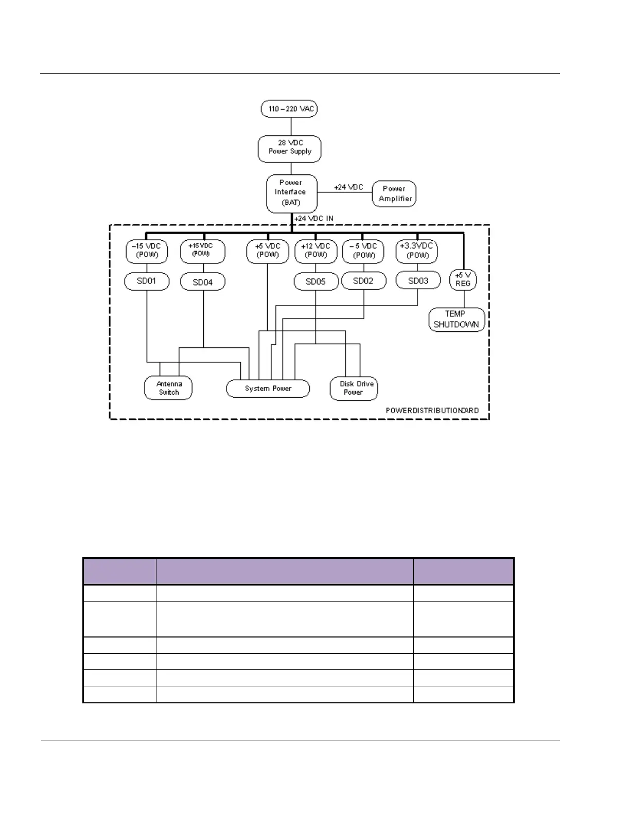
Figure 6-4: Internal Power Dependency
6:4. The sounder is protected by a 7.5 A circuit breaker in the main chassis, and a 30 A fuse in the power
amplifier chassis.
INTERNAL CABLING
6:5. Internal signal and power distribution has been logically divided into functional buses
as shown in Table 6-1.
Table 6-1: Signal and Power Buses
control bus for the receive antennas switches
connection between the control computer parallel port and the
sounder custom hardware mounted in the card cage via the Digital
Transmitter/Timing card
connects the system’s pre-processor card to the control computer
control bus for the power amplifier
supplies power to the card cage and antennas switches
conducts BIT sensor information