LDI Intellectual Property.
Not for secondary distribution or replication, in part or entirety.
DIGISONDE-4D
SYSTEM MANUAL
VERSION 1.2.11
3-22 SECTION 3 - OPERATING INSTRUCTIONS
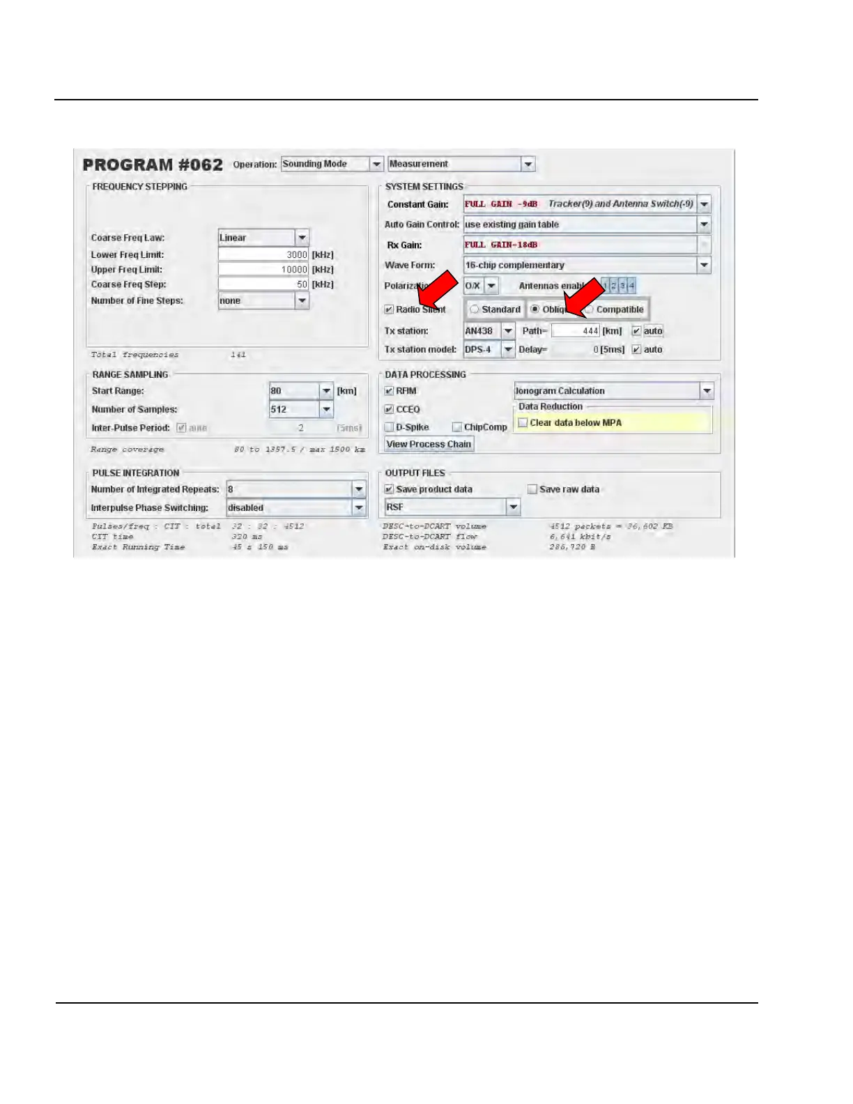
Figure 3-14: Digisonde-4D at Jeju Island, Korea, Configured to Receive Signal from Anyang DPS4
(444 km Ground Distance) Via Oblique Propagation.
3:38. For a Digisonde-4D to receive oblique incidence signals in addition to receiving its own vertical trans-
mission it is only necessary that the two stations be operating using exactly the same program and schedule def-
initions, and be physically close enough for oblique reception to occur.
Programming Drift Measurement
3:39. Sample drift measurement and real-time screen display of raw drift data are shown in Figure 3-15. As
explained previously in Paragraph 3:9, 3:18 and 3:19, the drift measurement is programmed to ensure high co-
herent integration time (CIT) and to reduce data volume by running a small number of fixed frequencies and
output ranges. For the example shown in Figure 3-15,
A. the CIT is set at 20.48 seconds by using N of 128 (maximum supported by the DFT file format), 10 ms in-
ter-pulse period, and 8x CIT increase by frequency multiplexing,
B. 8 frequencies spaced by 50 kHz are used with the lower frequency limit set at the ARTIST-recommended
value, and
C. 8 best ranges are picked for file storage by looking for the strongest echo in the interval of ranges between
140 and 500 km, which ensures that Digisonde
®
observes plasma drift in the F region.
The real-time display shows data from 4 receiver channels (spectral amplitudes in the left panel, and phases in
the right panel), selected at the best height out of 8 available as determined by the maximum signal strength.