LDI Intellectual Property.
Not for secondary distribution or replication, in part or entirety.
DIGISONDE-4D
SYSTEM MANUAL
VERSION 1.2.11
SECTION 2 - INSTALLATION, SETTING UP AND FIELD VALIDATION 2-15
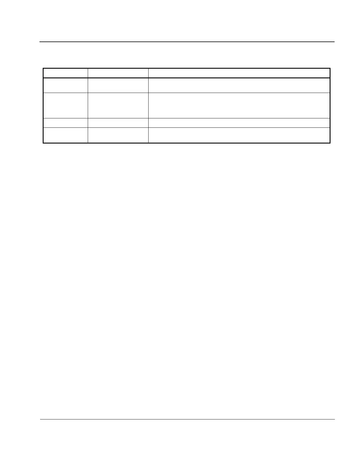
Table 2-1: Software Configuration Files Holding Site-Specific Data
Defines the Station ID for the sounder, stores configuration data for DCART pro-
cessing
xxx.UDD
(xxx = Station ID)
/digisonde/dispatch/resou
rces/UDD
Station UDD file. Provides station constants for post-processing and visualization
software. Stores records of changes to ensure that retrospective data are processed
correctly. Station ID files are kept at LDI under version control management and
distributed together with the analysis software to other users of Digisonde
®
data
Provides station constants for the DDAV software
Stores time zone specifics and text of labels for the web scripts supporting homep-
age operations of the sounder
RECEIVER ANTENNA ARRAY CONFIGURATION
2:52. Knowledge of antenna array configuration is required for interpretation of oblique beam codes stored in
directional ionograms and for all software that processes four-channel data.
2:53. Four-channel data are processed using full specification of the antenna array given in the Station UDD
file. Full specification of any antenna array (standard or non-standard) includes:
ANTENNA POSITIONS (X,Y,Z) specified in the right-hand system of coordinates with the central an-
tenna #1 placed at the origin (0,0,0) and Z axis pointing up.
DECLINATION ANGLE of the X axis of the coordinate system from Geographic North Pole, using posi-
tive angles for clockwise direction from X axis towards the North Pole.
NOTE
It is customary to select X axis parallel to a side of antenna array and pointing towards North (see
Figure 2-3, where X axis is line connecting antenna #2 and #3). In this case Y Axis of the coordi-
nate system points due West.
2:54. Aligning antenna pattern with respect to the Geographic North as in the Figure 2-3 is preferable, in
which case the X-axis Declination Angle is zero. Use of the ground level compass North to orient the anten-
na array is often more convenient. Such orientation is acceptable, as long as the X-axis Declination Angle at
the time of installation (equal to the Declination angle of the magnetic field) is recorded in the Station UDD
file.
2:55. When antenna field allows placement of antennas in one of the standard configurations, the following
parameters are specified for the software that processes four-channel data:
ANTENNA LAYOUT, which can be standard or mirror (Figure 2-7). In the standard Antenna Layout,
enumeration of antennas 2-3-4 goes counter-clockwise. In the mirror Antenna Layout, an-
tennas 2-3-4 are enumerated clockwise. In either cases, the antenna triangle is equilateral
with the length of the side specified as ANTENNA MAXDIST. Table 2-2 specifies An-
tenna Positions for standard and mirror configurations in the assumption of the X axis go-
ing from antenna 3 to antenna 2.
ANTENNA MAXDIST is the maximum distance between any two antennas in the configuration.
ANTENNA DEVN is the deviation angle of the line connecting antenna 3 and 1 from the X axis of the an-
tenna coordinate system, positive for counter-clockwise deviation.