LDI Intellectual Property.
Not for secondary distribution or replication, in part or entirety.
DIGISONDE-4D
SYSTEM MANUAL
VERSION 1.2.11
2-16 SECTION 2 - INSTALLATION, SETTING UP AND FIELD VALIDATION
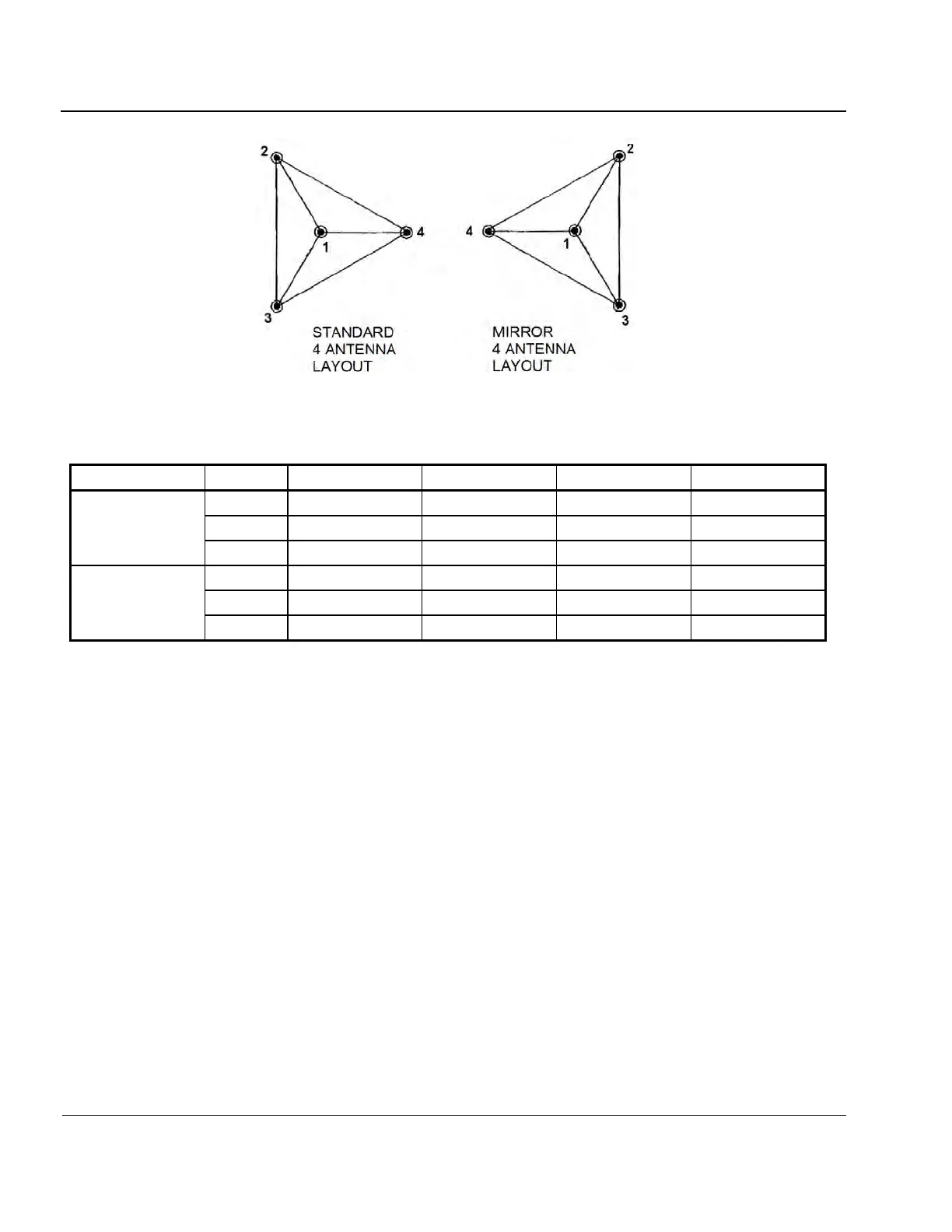
Figure 2-7: Two Common Digisonde-4D Antenna Layouts
Table 2-2: Antenna Positions for Standard and Mirror Antenna Layouts (Assuming MAXDIST of 60 m)
2:56. For the standard Digisonde-4D antenna configuration depicted in Figure 2-3:
e. ANTENNA LAYOUT is STANDARD,
f. ANTENNA MAXDIST is 60 m,
g. ANTENNA DEVN is -30 degrees, and
h. DECLINATION ANGLE is 0 degrees.
2:57. For antenna configurations that deviate from the equilateral triangle as in the Figure 2-7, ANTENNA
LAYOUT is NON_STANDARD and only ANTENNA POSITIONS and DECLINATION ANGLE are ap-
plicable.
2:58. Directional ionogram data are processed using reduced specification of the antenna array given in the
Station UDD file. Ionogram visualization software uses reduced specification to interpret beam codes stored
in the ionogram file. Reduced specification of any antenna array is:
ANTENNA PATTERN, which can be one of the following four options:
0 = Standard per manual
1 = Rotated 180 degrees
2 = Mirror
3 = None of the above