LDI Intellectual Property.
Not for secondary distribution or replication, in part or entirety.
DIGISONDE-4D
SYSTEM MANUAL
VERSION 1.2.11
1-24 SECTION 1 - GENERAL SYSTEM DESCRIPTION
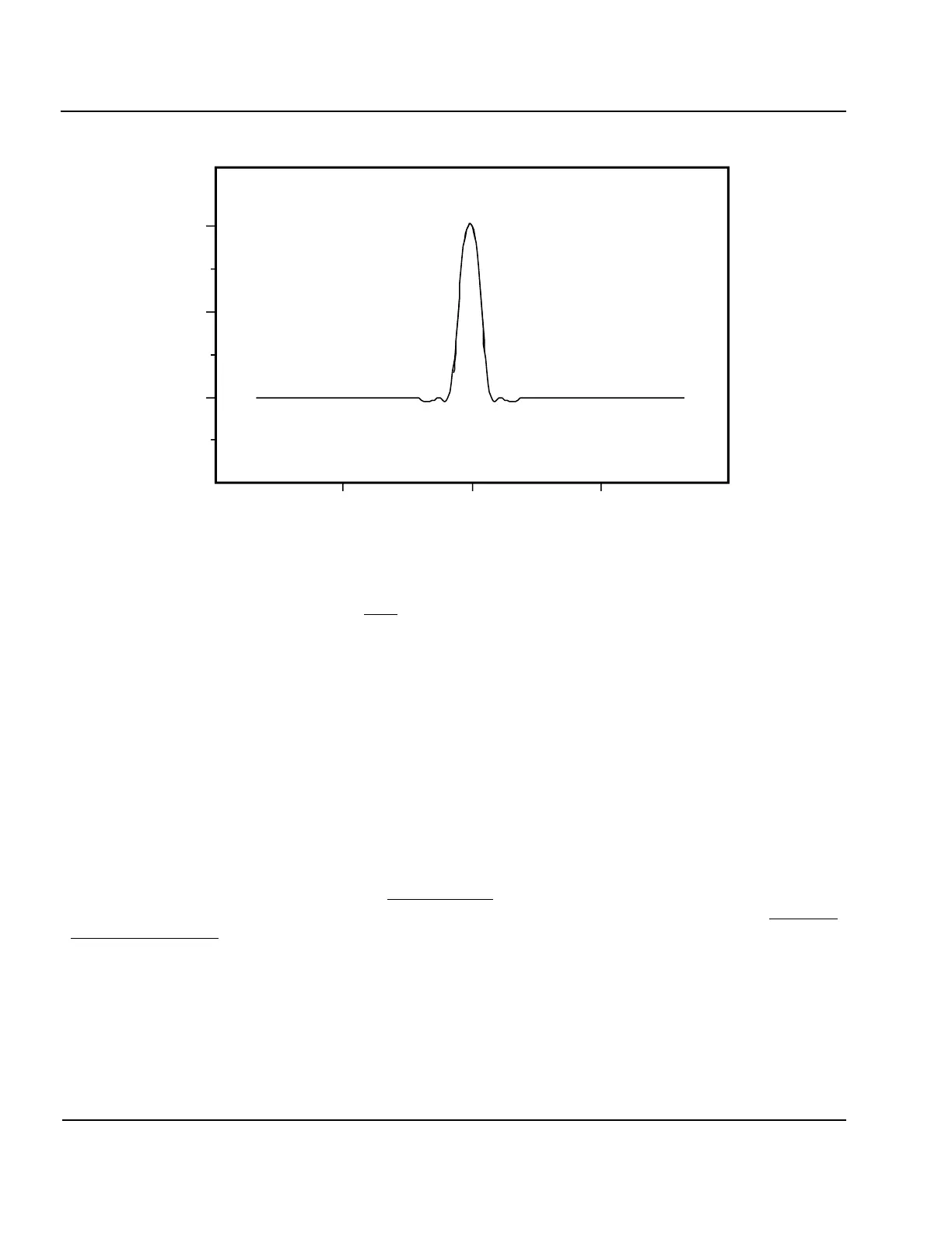
Figure 1-15: Autocorrelation Function of the Complementary Series
1:46. Since the Complementary Series pairs do not leak energy into any other height bin this phase code
scheme seemed optimum and was chosen for the Digisonde-4D vertical incidence measurement mode in order
to provide the maximum possible dynamic range in the measurement. If there is too much leakage (for instance
at a –20 dB level) then stronger echoes would create a “leakage noise floor” in which weaker echoes could not
be detectable.
1:47. Even though the Complementary Code pairs are theoretically perfect, the physical realization of this
signal may not be perfect. The Complementary Code pairs achieve zero leakage by producing two compressed
pulses (one from each of the two codes) which have the same absolute amplitude spurious correlation peaks (or
leakage) at each height, but all except the main correlation peak are inverted in phase between the two codes.
Therefore, simply by adding the two pulse compression outputs, the leakage components disappear. Since the
technique relies on the phase distance of the propagation path remaining constant between the sequential
transmission of the two coded pulses, the phase change vs. time caused by any movement in the channel geom-
etry (i.e., Doppler shift imposed on the signal) can cause imperfect cancellation of the two complex amplitude
height profile records. Therefore, the Complementary Code is particularly sensitive to Doppler shifts since
channel induced phase changes which occur between pulses will cause the two pulse compressions to cancel
imperfectly, while with most other codes we are only concerned with channel induced phase changes within the
duration of one pulse. However, if given the parameters of the propagation environment, we can calculate the
maximum probable Doppler shift, and determine if this yields acceptable results for vertical incidence sound-
ing.
1:48. With 200 pps, the time interval between one pulse and the next is 5 msec. If one pulse is phase modu-
lated with the first of the Complementary Codes, while the next pulse has the second phase code, the interval
over which motions on the channel can cause phase changes is only 5 msec. The degradation in leakage can-
cellation is not significant (i.e., less than –15 dB) until the phase has changed by about 10 degrees between the
two pulses. The Doppler induced phase shift is:
0
VIS1- 9
0.1
0.05
1 2
3
TIME ( msecs )