LDI Intellectual Property.
Not for secondary distribution or replication, in part or entirety.
DIGISONDE-4D
SYSTEM MANUAL
VERSION 1.2.11
SECTION 4 – HARDWARE DESCRIPTION 4-11
by Atmel. It takes about 2 μs for the PIC18LF6520 to accept one byte over the P-Bus, well below the P-bus
timeout of 10 μs. To ensure deterministic synchronism of bus operations, the microcontroller is clocked with
a 15.36 MHz signal derived from the master 61.44 MHz clock.
The AD9857 up-converters use the serial command interface, thus assigning the first task to the micro-
controller to translate the parallel bytes from the system control bus to a serial 8-bit sequence. Direct routing
of the incoming control bytes to the transmitter is done in so-called “pass-through” mode of micro-controller
operations.
Transmitter Output Modes
4:15. Phase-aware multiple-channel RF instrumentation requires an additional design effort to have cross-
channel differences in transfer functions calibrated out. In addition to the standard mode of transmitter opera-
tion when the output from the up-converters is routed to the RF power amplifiers, an internal loopback mode
is available to support cross-channel equalizing (CEQ) operations. In the internal loopback mode, a small
calibration signal is routed to the antenna switch, instead of the RF power amplifiers, for direct input to the
receiver channels. Transmission modes are realized by using switches within the antenna switch that ensure
signals are present on either two main outputs or CEQ output.
Transmitter Card
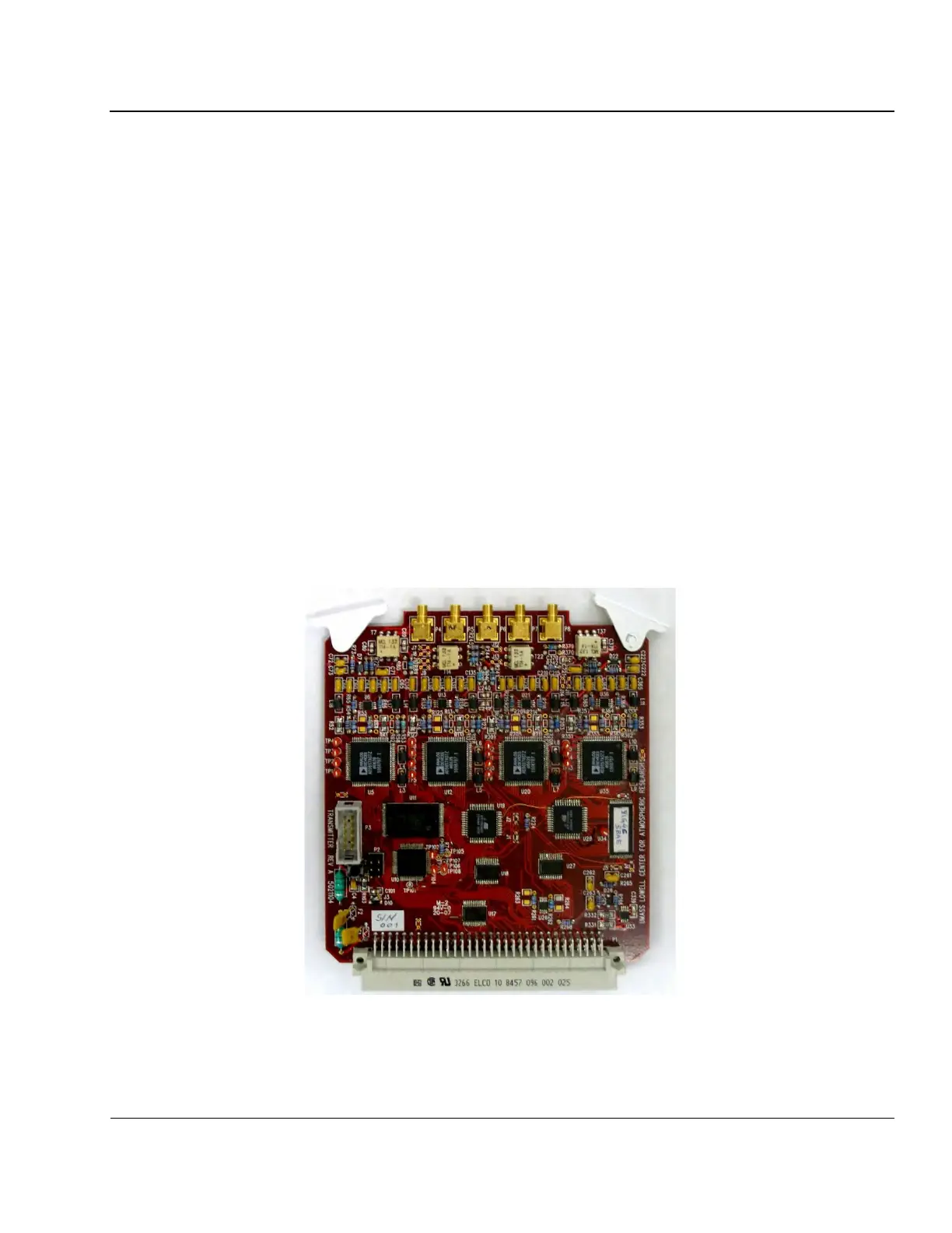
4:16. Figure 4-7 shows the transmitter card in its four-channel version (presently only two channels are
used in the DPS4D with the currently available software).
Figure 4-7: Transmitter PCB