LDI Intellectual Property.
Not for secondary distribution or replication, in part or entirety.
DIGISONDE-4D
SYSTEM MANUAL
VERSION 1.2.11
5-58 SECTION 5 - SYSTEM SOFTWARE – ANNEX B
Enable tracker band switching
1 = enable, normal operational mode (always 1 in opera-
tional state)
0 = disable, only for band’s width and shape testing
2 x (COMMAND BYTE, DATA BYTE)
This data are sending to DAC to provide correction of
voltage to Digisonde
®
general clock Oven Controlled 61.44
MHz Oscillator. This is DCART Global parameter. It need
to be tuned for every particular Digisonde
®
.
Controlling address for DESC to command is 0x2C.
It is two possible ways to command:
First - command byte 0x01, data XX
Second - command byte 24, data XX
or
First - command byte 0x05, data XX
Second - command byte 20, data XX
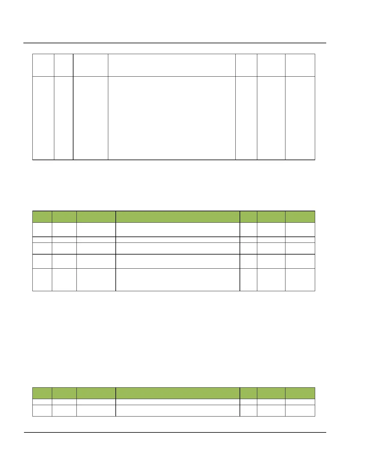
Trackers Calibration Data packet TYPE=0x06, Payload length is variable
5:137. DCART sends the Load Tracker Calibration Data packet at the time of the connection. This packet con-
tains information needed for tuning hardware to any particular frequency.
Table 5B- 10: Trackers Calibration Data packet TYPE=0x06, Payload length is variable
Schedule Number (0 means manual start of sounding)
Trackers Calibration Program Specification (Table 5A-
10 - Table 5A- 12)
Voltages.
Each voltage occupies one byte and corresponds to its
tuning frequency in the Trackers Band List described in
PROG structure
5:138. This is exactly the same structure as for Payload Trackers Calibration which is created by DESC as the
result of running Trackers Calibration program.
Amplifier Half-Octave Filter Switch Frequencies Table TYPE=0x86, Payload length is variable
5:139. DCART sends the Amplifier Half-Octave Filter Switch Frequencies Table at the time of the connection.
This packet contains information needed to switch amplifier to the correct filter band for any particular fre-
quency.
Table 5B- 11: Amplifier Half-Octave Filter Switch Frequencies Table TYPE=0x86,
Payload length is variable
Size – number of switch Frequencies
List of Switch Frequencies