LDI Intellectual Property.
Not for secondary distribution or replication, in part or entirety.
DIGISONDE-4D
SYSTEM MANUAL
VERSION 1.2.11
5-38 SECTION 5 - SYSTEM SOFTWARE – ANNEX A
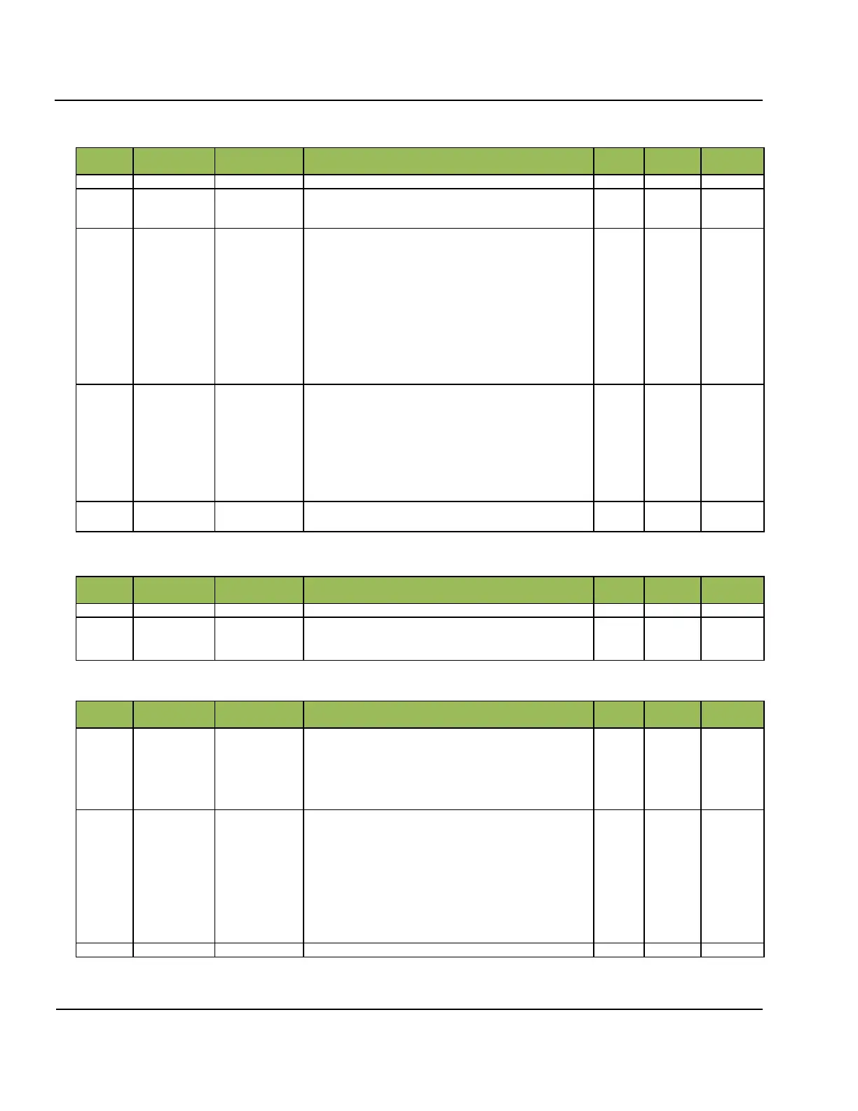
Table 5A- 10: Trackers Calibration Operation Version 3 (29 Bytes)
Operating code. Contains constant 4.
0 = Measurement
1 = Internal loopback
2 = SW (software) test pattern
Constant Gain
In OP_OPTION = Measurement
0 = full gain
1 = -9 dB in Antenna Switch
2 = -9 dB in Tracker
3 = -18 dB in Tracker and Antenna Switch
In OP_OPTION = Internal loopback
0 = full gain
1 = -9 dB in Antenna Switch
2 = -18 dB in Tracker and Antenna Switch
3 = -35 dB in Tracker and Antenna Switch
Rx Gain
0 = +30 dB
1 = +24 dB
2 = +18 dB
3 = +12 dB
4 = +6 dB
5 = 0 dB
6 = -6 dB
7 = -12 dB
Trackers Bands structure (see Table 5A- 11)
Table 5A- 11: Trackers Bands (Variable Length)
structTrucker-
BandLength *
BND_QTY
Array of Trackers Bands (see Table 5A- 12)
Elements should be in increasing order of Start Trackers and
without duplicating them.
Table 5A- 12: Tracker Band (Length 5 Bytes)
Start of Tracker Band.
Note:
There is no End of Tracker Band in this structure, but having
in mind this structure is used only as an element of array, the
End of Tracker Band is equaled to the Start Frequency of
next element in array.
Step inside band.
All tuning frequencies in the band are given as follows:
1
st
tuning frequency is equal to START_FREQ,
2
nd
tuning frequency is equal to 1
st
+ STEP_FREQ,
3
rd
tuning frequency is equal to 2
nd
+ STEP_FREQ,
etc.
up to, but not including, the End of Band
Note:
Value 0 means that START_FREQ is the only tuning fre-
quency in the band
Commanding byte to select band


 To Next Page