LDI Intellectual Property.
Not for secondary distribution or replication, in part or entirety.
DIGISONDE-4D
SYSTEM MANUAL
VERSION 1.2.11
SECTION 1 - GENERAL SYSTEM DESCRIPTION 1-35
1:74. Both techniques utilize the basic principle of interferometry, which is illustrated in Figure 1-21. This
phenomenon is based on the free space path length difference between a distant source and each of some num-
ber of receiving antennas. The phase difference () between antennas is proportional to this free space path
difference (l) based on the fraction of a wavelength represented by l.
l = d sin and
= (2pl)
/
= (2 d sin)
/
where is the zenith angle, d is the separation between antennas in the direction of the incident signal (i.e., in
the same plane as is measured), and is the free space wavelength of the RF signal. This relationship is used
to compute the phase shifts required to coherently combine the four antennas for signals arriving in a given
beam direction, and this relationship (solved for ) is also the basis of determining angle of arrival directly from
the independent phase measurements made on each antenna.
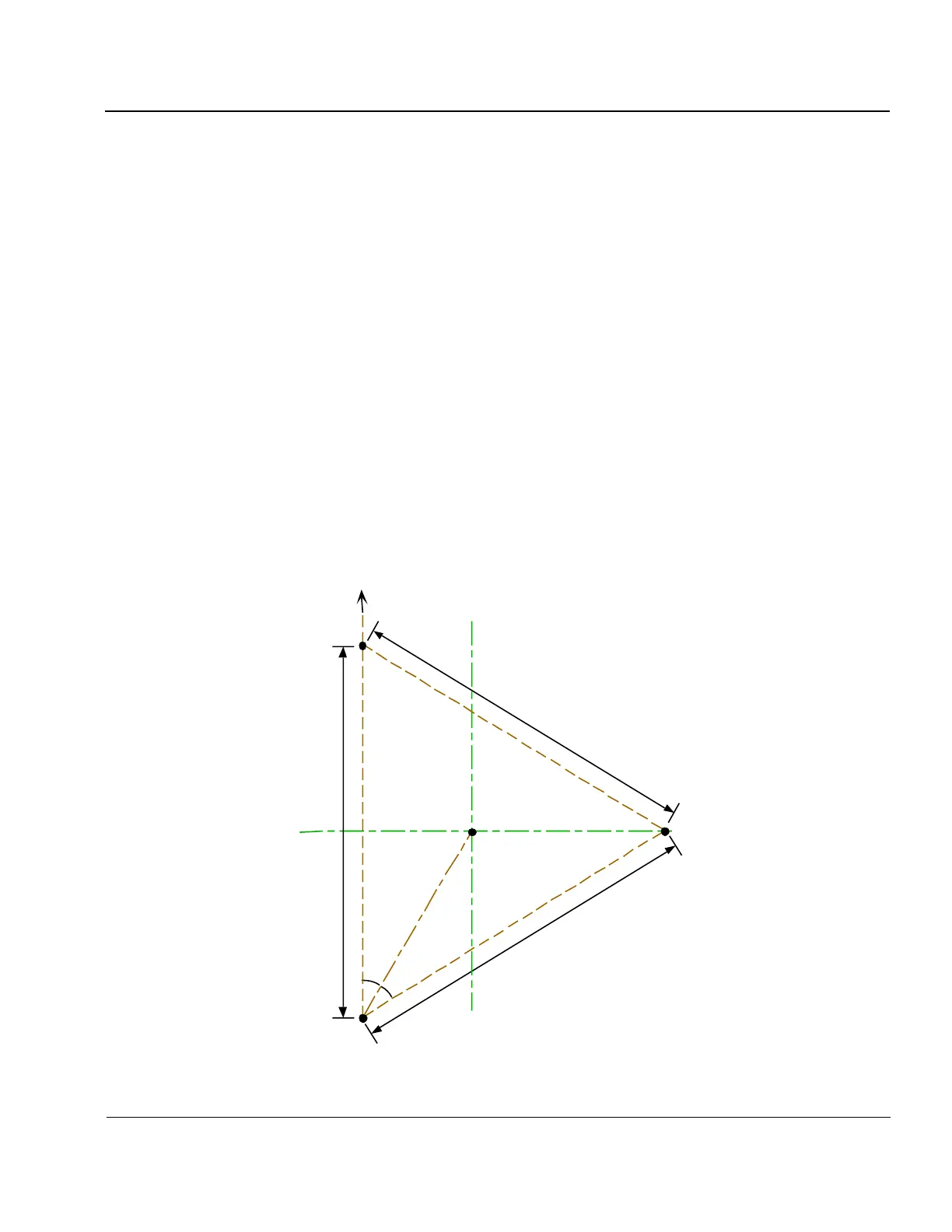
1:75. Figure 1-22 shows the physical layout of the four receiving antennas. The various separation distances
of 17.3, 34.6, 30 and 60 m are repeated in six different azimuthal planes (i.e., there is six way symmetry in this
array) and therefore, the ’s computed for one direction also apply to five other directions. This six-way
symmetry is exploited by defining the six azimuthal beam directions along the six axes of symmetry of the ar-
ray, making the beamforming computations very efficient. Section 2 of this manual contains detailed infor-
mation for the installation of receive antenna arrays.
Figure 1-22: Antenna Layout for 4-Element Receiver Antenna Array
#1
#2
#4
#3
60 m
60 m
60 m
Magnetic North
30
30
17.32 m 34.64 m
30 m
30 m
VIS3-3