LDI Intellectual Property.
Not for secondary distribution or replication, in part or entirety.
DIGISONDE-4D
SYSTEM MANUAL
VERSION 1.2.11
1-20 SECTION 1 - GENERAL SYSTEM DESCRIPTION
since the multiple carriers (from the various multipath components) cannot be resolved, while the delays in the
complex code modulation envelope can be, a separate term,
i
, is used. Next, when the carrier is stripped off of
the signal, this RF phase term will be represented by a complex amplitude coefficient
i
rather than a
i
.
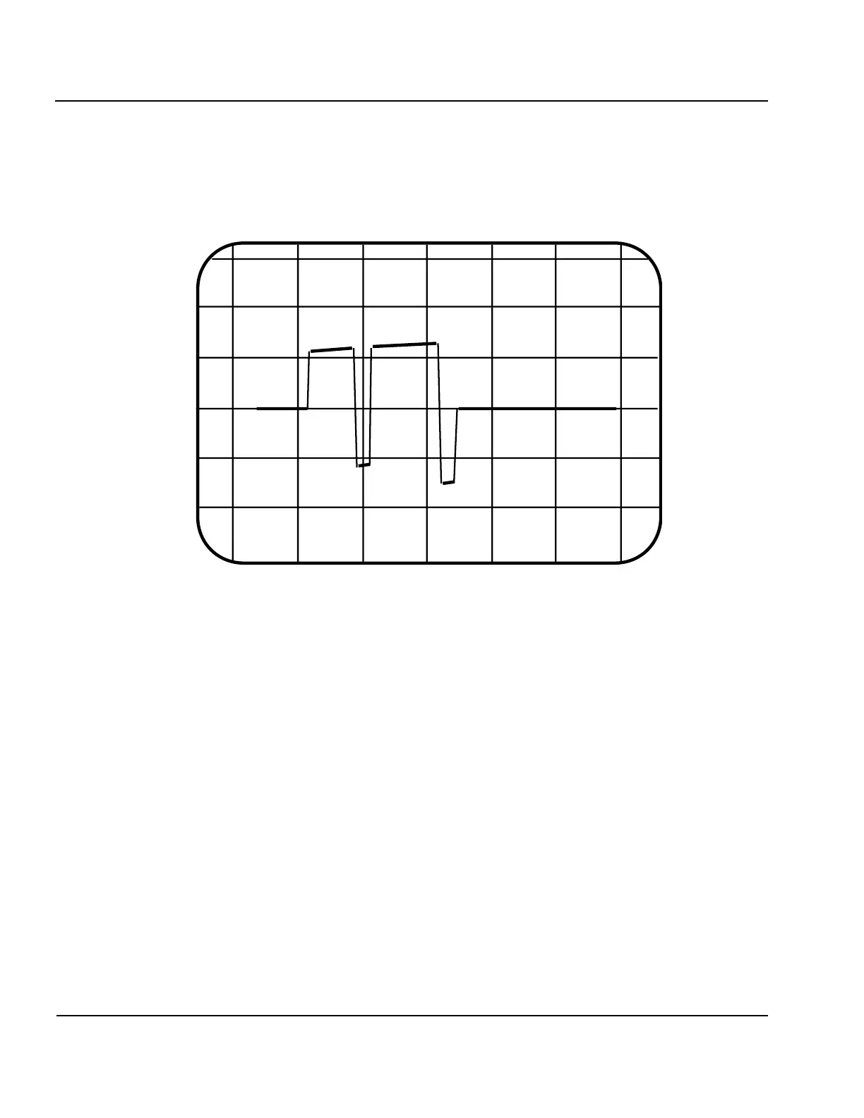
Figure 1-12: Conversion to Baseband by Undersampling
1:38. By down-converting to a baseband signal (a digital technique is shown in Figure 1-12), the carrier sig-
nal can be stripped away, leaving only the superposed code envelopes delayed by P multiple propagation paths.
Figure 1-12 presents one way to strip the carrier off a phase modulated signal. This is the screen display on a
digital storage oscilloscope looking at the RF output from the DPS system operating at 3.5 MHz. Notice that
the horizontal scan spans 2 msec, which if the oscilloscope was capable of presenting more than 14,000 resolv-
able points, would display 7,000 cycles of RF. The sample clock in the digital storage scope is not synchro-
nized to the DPS, however, the digital sampling remains coherent with the RF for periods of several millisec-
onds. The analog signal is digitized at a rate such that each sample is made an integer number of cycles apart
(i.e., at the same phase point) and therefore looks like a DC level until the phase modulation creates a sudden
shift in the sampled phase point. Therefore the 180º phase reversals made on the RF carrier show up as DC
level shifts, replicating the original modulating code exactly. The more hardware intensive method of quadra-
ture demodulation with hardware components (mixers, power splitters and phase shifters) can be found in any
communications systems textbook, such as [Peebles, 1979]. After removing the carrier, the modified r(t), now
represented by r
1
(t) becomes:
1 Volt/Div
Time (0.2 msec/Div)
VIS1- 6