LDI Intellectual Property.
Not for secondary distribution or replication, in part or entirety.
DIGISONDE-4D
SYSTEM MANUAL
VERSION 1.2.11
4-24 SECTION 4 – HARDWARE DESCRIPTION
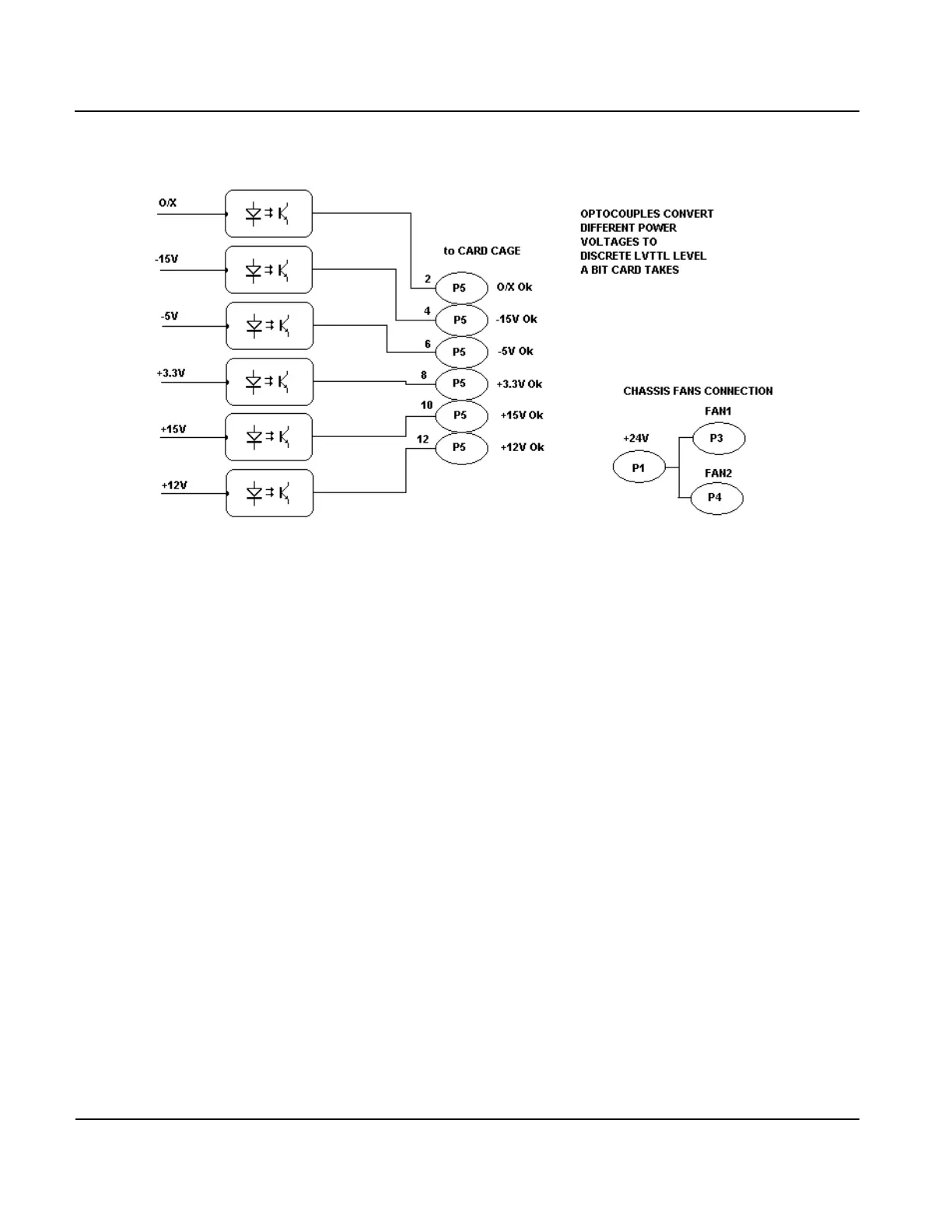
Figure 4-20: Power Distribution Card Block Diagram (BIT Card Interface)
POWER INTERFACE BOX
4:45. The functions of the power interface are to provide:
a) power connections to the VIS chassis, the RF Amp, and the cooling fans
b) remote switching on/off of all power via connection to J8/J9
c) a digital voltmeter to monitor the +28V power supply output.
d) In previous versions of the DPS4D the power interface served also as a battery interface and provid-
ed over voltage, under voltage, and over current protection. LDI can supply information about the
older versions upon request.
4:46. Upon power up or opening the external connection between J8 and J9, the two parallel P-channel
power MOSFETS (Q4 and Q5) are turned on, and current is provided to the RF Amp, VIS chassis, and cool-
ing fans through the terminal strip connections on top of the Power Interface Box housing.